


Checks and Adjustments
1705A Spectrum Monitor
5-5
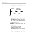
s. CHECK -- that the readout still reads 1000, ±10.
u. CHECK -- that the marker is on screen.
v. CHECK -- that the readout still reads 1000, ±10.
x. CHECK -- that the marker is on screen.
12. Check L--Band Gain and Flatness
e. CHECK -- that the marker is on the same crt center line (vertically),
±0.5 Division.
g. CHECK -- that the marker is on the same crt line (vertically), ±0.5
Division.
j. CHECK -- that the marker tip is on the --10 reference line, ±0.5
Division. Note: Make sure that the baseline is on the -- 70 graticule
reference line.
13. Check Positioning Range
b. CHECK -- that the tip can be positioned 2 Divisions left and right of
center.
e. CHECK -- that the marker tip can be positioned 3 Divisions down from
its present position.
f. CHECK -- that the baseline can be positioned to the --30 graticule line.
14. Check2dB/DivGain
g. CHECK -- for more than 1 Division of amplitude change.
h. CHECK -- that the noise floor can be positioned on screen.
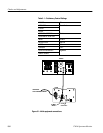
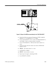
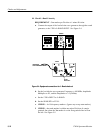
1. Preliminary Setup
a. Connect the 1705A ac power cord to the variable autotransformer. Turn
power on and set the autotransformer to the local nominal mains voltage
(110 V or 220 V). Allow 15 minutes for warm-up time before continu-
ing.
b. Set up the 1705A as shown in Table 5 --1.
Long Form Procedure
Test Equipment Depot - 800.517.8431 - 99 Washington Street Melrose, MA 02176 - FAX 781.665.0780 - TestEquipmentDepot.com