


Maintenance
6-12
1705A Spectrum Monitor
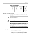
all obvious defects. In the case of overheated components, determine and
correct the cause of overheating before re-applying power.
5. Use successive electrical checks to locate the source of the problem.The
primary tool for problem isolation is the oscilloscope. Use the Performance
Check Procedure (located in Section 5) to determine if a circuit is operating
within specifications. At times it may be necessary to change a calibration
adjustment to determine if a circuit is operational, but since this can destroy
instrument calibration, care should be exercised. Before changing an
adjustment, note its position so that it can be returned to its original setting.
6. Determine the extent of the repair
. If the necessary repair is complex, it may
be advisable to contact your local Tektronix field office or representative
before continuing. If the repair is minor, such as replacing a component, see
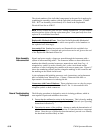
the parts list for replacement information. Removal and replacement
procedures for the assemblies can be found under Corrective Maintenance.
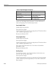
Power Supply Troubleshooting Procedure
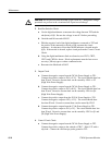
NOTE. A review of the pow er supply theory of operation is recommended before
attempting repairs.
The equipment needed to troubleshoot the power supply:
H Digital Multimeter (DMM), with a diode check function
H Oscilloscope
H 0 to 20 Vdc Variable Power Supply
H Clip Lead -- to short across a component
H High Voltage Probe, ≥1GΩ input resistance
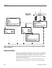
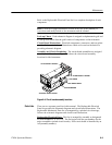
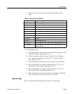
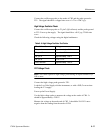
The Troubleshooting P rocedure for the Power Supply (Assembly A1) is split into
two sections, the Low Volts and High Volts Supplies. Start the procedure by
determining which section of the Power Supply the problem is in. Apply ac
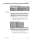
power and turn on the Power Supply. From Table 6--2, determine which
symptom the Power Supply exhibits and refer to the corresponding procedure.
Table 6- 2: Power Supply Fault Symptoms
Symptom Procedure
Line fuse open Rectifier/Switcher Check (Low Volts)
Introduction