


Checks and Adjustments
1705A Spectrum Monitor
5-13
ALIGN 2nd
MARKER HERE
DISREGARD
#1
GRATICULE
LINE
#2
GRATICULE
LINE
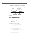
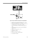
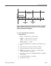
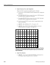
Figure 5-5: Aligning L- Band time markers with the graticule lines. The graticule
begins with 0 while the time markers are counted 1, 2, 3, etc. The first and last
divisions of sweep should be disregarded
11. Check L--B and SPAN/DIV an d Readout
REQUIREMENTS:
FULL — 1 marker/Division ±1 minor Division
10 MHz — 1 marker/5 Divisions ±1 Division
1MHz— 1 marker/5 Divisions ±1 Division
Readout Accuracy — ±20 MHz.
a. Set CENTER FR EQUENCY to 1400 MHz, and set SPAN/DIV to 10
MHz.
b. Set the leveled sine wave generator Frequency to 50 MHz.
c. Position the readout caret to center of screen horizontally.
d. CHECK -- for 1 marker every 5 Divisions, ±1 Division (adjust
CENTER FREQUENCY, if necessary).
e. Repeat parts a. through d. with CENTER FREQUENCY at 950 MHz
and 1700 MHz.
f. Set CENTER FREQUENCY to 1400 MHz.
g. Set SPAN/DIV to 1 MHz.