


Operating Instructions
2-4
1705A Spectrum Monitor
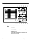
11. HORIZONTAL
A variable control that positions the trace horizontally (X axis).
12. VERTICAL
A variable control that positions the display vertically (Y axis).
13. POWER
Switches the instrument between a powered up state and standby. Portions
of the Power Supply circuit board have mains potential on them in either
state. A mechanical indicator in the center of the switch shows the status of
the POWER switch.
WARNING. Mains power is still applied to the 1705A Power Supply circuit board,
regardless of POWER switch state. To totally remove shock hazard, it is
necessary to unplug the instrument and wait for the capacitors to discharge.
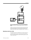
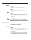
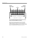
Rear-Panel Connectors
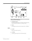
Signal input and power input are located on the 1705A rear panel. See Fig-
ure 2-2 for the locations of the rear-panel connectors.
1. L--BAND
A75Ω input f-type connector used for the 900 -- 2000 MHz input of L--Band
rf, which is down converted by a Low-Noise Amplifier/Block Down
Converter (LNB) from the received satellite signal.
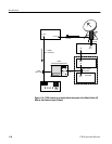
2. LNB POWER (Switch)
Switch to turn on or off the +18 V supply on the L--BAND INPUT connec-
tor. Supply is normally used to power a Low-Noise Amplifier/Block Down
Converter at the antenna.
POSITION
POWER
INPUTS