


Maintenance
1705A Spectrum Monitor
6-11
3. Determine and evaluate all trouble symptoms
. This is accomplished by
isolating the problem to a general area such as an assembly. The block
diagram is a valuable aid in signal tracing and circuit isolation.
CAUTION. Use extreme care when probing with meter leads or probes, because of
the high component density and limited access within the instrument. The
inadvertent movement of leads or a probe could cause a short circuit or transient
voltages capable of destroying components.
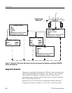
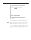
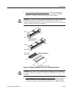
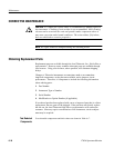
Circuit board
mounted pins
PIN 1
Moveable 10--pin plug
Square pin connector on
power supply circuit board
PIN 1
PIN 1
24 and 34 pin circuit
board connectors on
Main circuit board
ROW A
ROW B
ROW B
ROW A
Figure 6-7: Multiple pin connectors used in the 1705A Spectrum Monitor
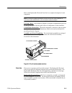
CAUTION. Always remove the assembly from the instrument prior to attempting
to replace a soldered-in component. See Corrective Maintenance for the correct
procedure.
4. Visually inspect the suspect assembly for obvious defects
. Most commonly
these will be broken or loose components, improperly seated components,
overheated or burned components, chafed insulation, etc. Repair or replace