


Maintenance
1705A Spectrum Monitor
6-19
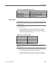
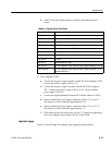
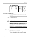
Table 6- 7: Test Selectable Components
Circuit Number Nominal Value Ra nge of Values Selection Criteria
R50
R74
R73
5.62K
3.40K
18.2K
2.7K to 8.2K
1K to 6.8K
18K to 27K
To correct nonlin-
earities of L--band
tuners.
R53 115.0K 115K to 130K To alter magnifier
range when ad-
justment range of
A3R38 is insuffi-
cient.
Mechanical Disassembly/Assembly
Use these instructions for disassembly and reverse them for reassembly, unless
otherwise noted.
WARNING. Before attempting any disassembly/assembly of the instrument, be
sure to disconnect the power cord.
CAUTION. Do not reinsert screws in the rear panel when the instrument is
removed from the cabinet.
NOTE. All screws, unless otherwise noted, are TORXǺ screws and can be
removed with a T15 screwdriver tip (Tektronix part number 003-0966-00). The
exception is #2 PozidriveǺ screwswhichcanberemovedwitha#1PozidriveǺ
tip (003-0443-00).
Do not reinsert screws in the rear panel when the instrument is removed from the
cabinet.
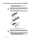
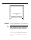
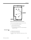
1. Remove the two bezel screws. See Figure 6-8.
2. Grasping the bottom of the bezel, pull out and upward. There are two hinges
at the top of the bezel that hold it in place; once the bezel is at an approxi-
mate 45° angle with the front panel, they will disengage.
Bezel Removal