


Checks and Adjustments
5-22
1705A Spectrum Monitor
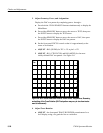
7. Adjust Readout Position
Display the DAC test pattern by completing parts a. through c.
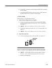
a. Press both the 1705A SPAN/DIV buttons simultaneously to display the
Main Menu.
b. Press either SPAN/DIV button to move the cursor to TEST, then press
the INPUT button to display the TEST menu.
c. Press either SPAN/DIV button to move the cursor to DAC , then press
the INPUT button to display the DAC test pattern.
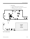
d. ADJUST -- R27 and R29 (HORIZ and VERT POSN READOUT) for a
display crossing at the crt center.
e. Exit the DAC test pattern by first pressing the INPUT button to display
the TEST menu.
f. Press either SPAN/DIV button to move the cursor to EXIT, then press
the INPUT button twice to return to a normal display.
8. Adjust 360/119.8 MHz L.O.
NOTE. Use an insulated tool for the following adjustments.
a. Adjust the VERTICAL POSITION control so that the crt trace is on the
--70 graticule reference line.
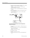
b. Connect the signal generator to J11 (480 MHz IF Input). Set the output
Frequency for 489.7 MHz and the Amplitude to --40 dBm.
c. Select 300 kHz RESOLUTION.
d. Set C55 to full mesh, C69 to 1/8 mesh, and L4 to the top of the coil
(three slug threads visible).
e. ADJUST -- FL1 for maximum signal (three screws beginning at the
outside adjustment screw). If no signal is present, adjust L4 down a few
turns and then adjust FL1.
f. ADJUST -- C55 for maximum signal. (C55 should peak at about 1/8 to
1/2 mesh.)
g. ADJUST -- F L1, center and inside screws (do not readjust the outside
screw), for maximum signal. (Less than one turn should be required.)
h. ADJUST -- FL2 for maximum signal (three screws beginning at the back
screw).