


Maintenance
6-16
1705A Spectrum Monitor
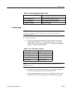
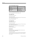
Table 6- 5: High Volts Supply Fault Symptoms
Symptom Procedure
Unable to focus crt using the front-
panel control
Focus Amplifier Check
Unable to adjust crt intensity using the
front-panel control
Z--Axis Amplifier Check
Grid Drive Check
No crt display High Voltage Oscillator Check
CRT Voltage Check
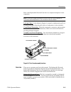
Load the Low Volts Supply with the instrument, or with the 20Ω resistor as
stated at the beginning of the Troubleshooting Procedure.
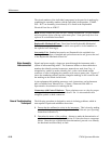
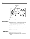
Focus Amplifier Check
Unsolder and lift one end of R24.
Power up the Power Supply.
Using the digital multimeter, measure the voltage between TP1 and the collector
of Q1. It should be approximately --140 V.
Reconnect the lifted end of R24.
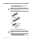
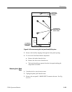
Z-Axis Amplifier Check
Unsolder and lift one end of R8.
Power up the Power Supply.
Using the digital multimeter, measure the voltage between TP1 and the collector
of Q4. It should be approximately +10 V.
Short together the base and emitter of Q5. The collector of Q4 should be
approximately +100 V.
Reconnect the lifted end of R8.
Grid Drive Check
Turn off the Power S upply. Use the digital multimeter’s diode check to test
CR1, CR2, CR3, CR5, and CR6 for shorts.
Power up the Power Supply.
Using the digital multimeter, measure the voltage between TP1 and the cathode
of CR5. It should vary between approximately +75 and +200 V as R58 (CRT
Bias) is adjusted.