


Maintenance
6-22
1705A Spectrum Monitor
BESCHLEUNIGUNGSSPANNUNGKLEINERALS
20kV
DIEINDIESEMGERA TENTSTEHENDE
RONTGENSTRAHLUNGISTAUSREICHENDABGESCHIRMT
TOAVOIDELECTRICALSHOCK,THEPOWER
CORDPROTECTIVEGROUNDINGCONDUCTOR
MUSTBECONNECTEDTOEARTHGROUND.
SPECTRUM MONITOR
70MHz
INPUT
L-BAND
INPUT
LNBPOWER
LNBPOWER
ON
OFF
+18VDC@250mA
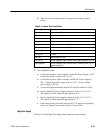
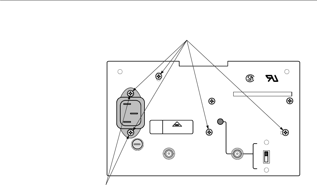
Remove these five (5)
screws to remove the
rear panel.
Secured by removeable
nuts inside the panel.
ON
WARNING
0.70MAX
50/60Hz
90-250V
REPLACEFUSEONLY
WITH
250V2AFTYPE
333-- 3990--01
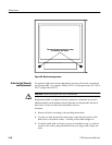
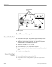
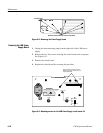
Figure 6-9: Screws securing the rear panel
1. Remove the five rear screws. See Figure 6-9. Screws securing the power
receptical use removeable nuts as fasteners inside the rear panel.
2. Unsolder the bnc and ground connections. (If 1700F10 Field Upgrade is
installed, unsolder leads from the battery connector. )
3. Unsolder the two leads to the +18 V switch.
4. Remove the hex nut on the L--BAND INPUT connector.
5. Pull the rear panel free from the chassis, be careful not to pull the unsoldered
wires.
6. To replace, reverse the procedure.
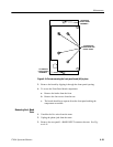
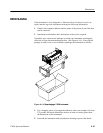
1. Remove the blue multiwire connector from J154.
2. Remove the two screws holding the board in place. See Figure 6-10 for
location.
Removal of the Rear Panel
Removal of Front- Panel
Assembly