


Checks and Adjustments
1705A Spectrum Monitor
5-3
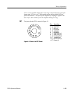
11. SMA Male-to-bnc Female Adapter
Two required (supplied with the Tektronix Comb Generator).
For example: Tektronix Part No. 015-1018-00.
12. SMB Female-to-bnc Female Adapter
For example: Coaxial Components Corporation P art No. 2525-4.
Performance Check
The Short-Form Procedure is intended for those who are familiar with the
complete Performance Check procedure. Step numbers and sub-step designa-
tions correlate directly to the steps in the Performance Check Procedure; this
makes it possible to use the Short-Form Procedure as a table of contents.
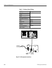
1. Preliminary Setup
a. Connect autotransformer.
b. Connect markers from Comb Generator.
2. Check Power Supply Operation
d. CHECK -- for stable operation over the prescribed voltage range.
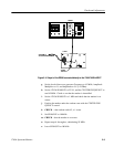
3. Check LNB Power Supply
c. CHECK -- that the rear -panel, red indicator lamp is lighted and that the
DVM reads +18 V ±0.9 V.
e. CHECK -- that the red indicator lamp extinguishes and then comes back
on when the short is removed.
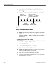
4. Check 70 MHz Linearity
c. CHECK -- for 10 frequency markers from beginning to end of sweep.
d. CHECK -- that each marker is within one minor Division of a major
graticule Division.
5. Check 70 MHz SPAN/DIV and Readout
d. CHECK -- for one mark every 5 major Divisions, ±1 major Division.
k. CHECK -- that readout reads 45, ±1 count.
m. CHECK -- that the marker is on screen.
Short-Form Procedure