


Maintenance
1705A Spectrum Monitor
6-25
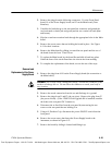
2. Remove the plugs from the following connectors: J1 to the Front-Panel
board, J4 on the Power Supply board, and J2 on the Main board (Trace
Rotation).
3. Unsolder the leads that go to the rear-panel bnc connector and ground the
two horizontal crt leads (red and green) and the two vertical crt leads (blue
and brown).
4. Slip the crt and trace rotation leads through the appropriate holes in the Main
board.
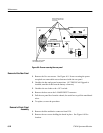
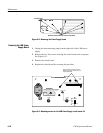
5. Remove the seven screws that are holding the board in place. See Figure
6-11 for their locations.
6. Remove the Main board by sliding it toward the rear panel until the toe of
the board clears the front. Then lift out.
7. To replace the Main board, lay the board flat and slide it back into place.
Guide the front of the circuit board into the slots in the front molding.
8. To complete the replacement of the board, reverse the rest of the steps.
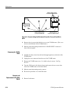
1. Remove the plug from A1J4 on the P ower Supply board (the connection to
the Main board).
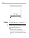
WARNING. The crt may retain a dangerous charge. Ground the conductor of the
anode to discharge the crt. Do not allow the conductor to touch your body or
any circuitry.
2. Remove the anode connection from the crt and discharge it to ground.
3. Remove the plugs from J1 and J3 (the crt wires). Remove the plug from J2
(the power switch). (If the 1700F 10 Field Upgrade Kit is installed, unsolder
the leads to the rear-panel DC Connector.)
4. Disconnect the ac line filter from the rear panel by unscrewing the two
screws on the rear panel that are holding it in.
5. Using a #1 PozidriveǺ tip, disconnect the power ON/OFF switch from the
front panel.
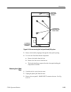
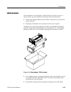
6. Remove the seven screws that fasten the Power Supply board to the
instrument, as shown in Figure 6-12.
7. Remove the board by sliding it forward and lifting it up.
Removal and
Replacement of the Power
Supply Board
Test Equipment Depot - 800.517.8431 - 99 Washington Street Melrose, MA 02176 - FAX 781.665.0780 - TestEquipmentDepot.com