


Checks and Adjustments
1705A Spectrum Monitor
5-25
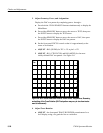
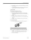
g. ADJUST -- R51, R58, R75, R81, and R82 for a linear display with each
marker on a g raticule mark, ±1 minor Division.
h. Readjust R35 to place first marker on the extreme left graticule.
NOTE. Readjustment of R35 may cause a change in linearity.
13. Adjust Readout Ran ge
a. Turn CENTER FREQUENCY fully counterclockwise.
b. ADJUST -- R4 (Readout Cal) so the frequency readout displays
900 MHz.
14. Adjust Span /Div Magnification Registration
a. Set SPAN/DIV to 1 MHz.
b. Turn the CENTER FREQUENCY control to position any marker under
the readout caret.
c. Set SPAN/DIV to 10 MHz.
d. ADJUST -- R27 (Horiz Posn Readout) to position the caret directly over
the marker.
e. Set SPAN/DIV to 1 M Hz. Marker should be under caret ±1 minor
Division.
f. Adjust the HORIZONTAL P OSITION control to place the caret at the
center of the screen.
g. If R27 requires adjustment, check step 10 parts a. through e. (R55), and
check step 12 parts a. through d. (R35).
15. Adjust Span /Div Magnifier Range
a. Set SPAN/DIV to 10 MHz.
b. Use the HORIZONTAL P OSITION control to position the caret to the
center screen graticule line.
c. Turn the CENTER FREQUENCY control fully clockwise (the readout
should display 2000 MHz ±50 MHz).
d. Set the signal generator Frequency to 1800 MHz, and Amplitude to --30
dBm.