


Maintenance
6-8
1705A Spectrum Monitor
Tek
REF
--10
--20
--30
--40
--50
--60
--70
L
O
G
+f
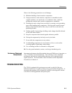
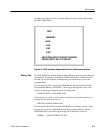
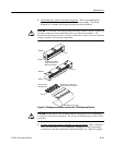
Figure 6-5: DAC check waveform used to check Focus, Astigmatism, Geometry, and
Trace rotation setting
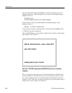
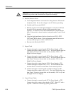
There are two additional diagnostic tests that can be made. The LED test
alternates high and low levels on the control lines to the front-panel indicators.
It can be used to either locate burned-out indicators (visual inspection of flashing
indicators) or shorted indicator lines (by probing with an oscilloscope).
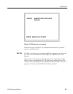
The Key test simply prints out the name of the key’s function when it is pressed.
In both cases the test is terminated by pressing the INPUT push button.
Troubleshooting Aids
Since this manual is also a troubleshooting aid, its organization is described here.
This material is general, and does not cover specific cases.
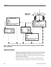
The foldout pages at the back of the manual contain block and schematic
diagrams, circuit board illustrations, and lookup charts.
Diagrams
. Schematic diagrams show the circuit number and electrical value of
each component. Symbols used on these diagrams are defined on the first page
of Section 9. Circuit boards are indicated by a heavy border.
Signals leaving or entering a schematic diagram are cross-referenced with the
connecting schematic number in brackets and the schematic grid location in
small print.
LED and Key Tests
Foldout Pages