


Introduction
1705A Spectrum Monitor
1-15
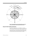
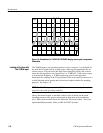
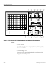
11.729GHz 11.788GHz 11.847GHz 11.906GHz 11.965GHz 12.024GHz 12.083GHz 12.142GHz
11.7585GHz 11.8175GHz 1 1.8765GHz 1 1.9355GHz 1 1.9945GHz 12.0535GHz 12.1125GHz 12.1715GHz
1
2
3
4
5
6
7
8
9
10
11
12
13
14
15
16
HORIZONTAL
POLARIZATION
VERTICAL
POLARIZATION
DOWN LINK
FREQUENCY
TRANSPONDER
NUMBER
FREQUENCY AND NUMBER
TRANSPONDER
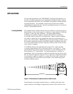
Figure 1-7: Transponder assignments for a typical Ku-Band, 16-transponder satellite that employs alternate
polarization (Not all Ku-Band satellites conform to these frequencies and/or this polarization scheme)
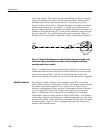
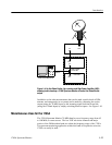
Once the satellite has been found it will be necessary to find the proper trans-
ponder and determine if it is available. With the 1705A frequency readout offset
correctly set up, it is possible to directly zero in on the correct transponder.
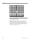
Figure 1-8 is a computer simulation of the 1705A Spectrum Monitor display in
FULL SPAN/DIVISION. Each division corresponds to 100 MHz. If the
satellite previously discussed is being looked at and the brightup is on the first
marker, then the first signal is transponder number 1 and the antenna feed horn is
horizontally polarized. Further, it is possible to determine that transponders 5, 7,
9, 13, and 15 are currently in use. Rotating the feed horn polarity 90˚ would
bring up a display of the vertically polarized transponder down links.
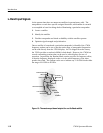
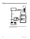
Once the correct satellite has been identified, minor adjustment to the antenna
position will optimize the link. The antenna azimuth and elevation can be fine
tuned for maximum signal strength and the opposite polarization carefully nulled
while observing the spectrum monitor crt screen.
Finding The Correct
Transponder
Optimize Signal Strength