


Introduction
1-10
1705A Spectrum Monitor
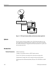
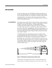
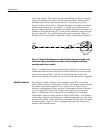
orbit of the satellite. If the orbit of an equatorial orbiting s atellite were roughly
equal to the distance from earth to the sun, ordinary latitude could be used to
determine the elevation of the antenna, which is, of necessity, very finely
focused. However since there is a disparity this angle is somewhat less than the
latitude for the earth station. See Figure 1-3. Simple logic readily points out
that as the latitude increases the angle from horizon to the satellite decreases. An
example of this would be that at 45˚ North or South latitude the angle above the
horizon is about 40˚ for a satellite at the earth station’s longitude. Figure 1-3
illustrates why it is not possible to pinpoint a satellite with ordinary navigation.
A
EARTH
SATELLITE
SUN
00°
(EQUATOR)
45° N
Figure 1-3: Angle A (the difference at a specific latitude between the angle to the
sun and the angle to a satellite) is the reason ordinary navigation techniques
cannot be used to find a satellite
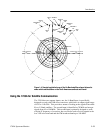
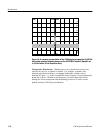
Figure 1-4 confirms that the angle from the prime meridian to a satellite will be
considerably different than the angle from a North American or European earth
station to the same satellite. It should also be noted that the elevation also
decreases for a satellite the further east or west from the earth station’s longitude.
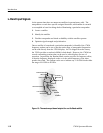
Even though a satellite, in theory, can communicate with 40% of the earth’s
surface from its location, in most cases it will not. The antenna systems onboard
the satellites are usually designed to cover a specific area. These areas are
referred to as hemispheres, zones, and spots. A hemispherical beam is designed
to cover roughly 40% of the earth’s surface, for example, the western hemi-
sphere. A zonal beam covers a specific area, for example, the Continental
United States, which is usually referred to as the CONUS beam. A spot beam is
exactly what it implies, concentrating on a smaller geographical area, such as the
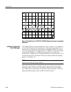
western United States. With each of these beams there are areas where the signal
strength is greater. Figure 1-5 shows a propagation map for the western spot
beam for one Ku--Band satellite.
Satellite Footprints