


Theory of Operation
1705A Spectrum Monitor
4-9
conditions the output goes toward the positive supply. If the input is between +
and --0.7 V, neither diode conducts and the amplifier has no input and, conse-
quently, an output of 0 V. When the output of U14D is near 0 V, a pulse that
produces the crt bright zone is generated by the Z--Axis Control circuit.
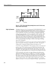
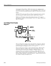
The Z--Axis Control circuit is comprised of a transistor array, U13, and discrete
transistors Q4 and Q5. The output is the common collector line of the three
differential amplifiers (Q5, and pins 5 and 8 of U13). The output line drives the
summing junction of the Z--Axis Amplifier on Diagram 8. The front-panel
INTENSITY control drives the current source (pins 12, 13, and 14 of U13). All
of the current from this transistor can be directed to the Z--Axis Amplifier,
through the differential amplifiers or shunted away if Q6 is turned on. Q6 is on
during sweep retrace, to blank the crt, and during crt readout time, when
/RO--EN is active (low). With Q6 off, the current from the source is split
between R54 and R79. The current through R54 is the collector current on pin 5.
The current through R79 will appear as collector current on pin 8 if its base
(pin 9) is low, which occurs at marker time. The result is that when the
instrument is in FULL SPAN, the trace is brightened for the marker. In any
other SPAN/DIV setting, the trace is of uniform brightness when the output of
U14D is near 0 V, a pulse that produces the crt bright zone is generated by the
Z--Axis Control circuit.
The readout intensity is controlled separately by Q4 and Q5. If the RO--BLANK
control line is active (low), Q4 is turned off and Q5 is turned on. When Q5 is
on, the current through R89 and R91 is sent to the Z--Axis Amplifier. When the
control line goes high, Q4 turns on and the emitter current from the readout
intensity control is directed into the +5 volt supply instead of into the Z--Axis
Amplifier.
Deflection Amplifiers
Diagram 4
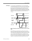
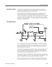
Circuitry on this schematic normalizes gains, and drives the crt deflection plates.
The vertical signal from the Log Detector is buffered by U27. U27 drives the
Vertical Output Amplifier, whose input can be filtered to reduce the effects of
noise. The Video Filter is a 15 kHz, 3-pole, low-pass filter whose output is
switched in by U30A. The enable, for U30A, is the /VFILTER signal from the
microprocessor (Diagram 5).
U27 is a switchable gain amplifier. When high gain (2 dB/Div) is selected with
the front-panel push button, the signal at pin 12 of the microprocessor (U2) goes
high, and the switch in U21C grounds R135 through pins 3 and 4. This
increases the gain of U27 by approximately a factor of five. U21A also
switches, connecting pins 13 and 14, putting a portion of the Vertical Position
Z- Axis Control
Buffers