


1705A Spectrum Monitor
2-1
Section 2
Operating Instructions
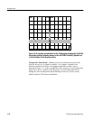
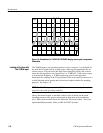
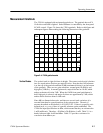
These instructions provide information about the front-panel controls and
indicators, rear-panel connectors and switch, powering-up, and the measurement
graticule and alphanumeric readout.
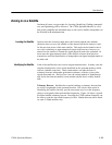
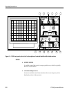
Front-panel Controls and Indicators
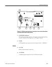
The front--panel controls and indicators consist of momentary contact push-but-
ton switches, with backlit switch selections, and variable controls. For front-
panel control and indicator locations, see Figure 2-1. There are also functions
that are accessed by holding the switch down for approximately 1 second. These
functions are identified by a blue box surrounding the front--panel label.
1. VIDEO
Turns on or off the Video Filter, which reduces the post detection bandwidth
(video), to reduce the high-frequency components for display noise
averaging. A front-panel LED indicator lights when the Video Filter is on.
Holding the Video s witch activates the High Gain mode. An on-screen
readout indicates 2 dB/Div. To exit this mode, hold the switch again, and the
on-screen readout returns to 10 dB /Div. Gain selection will not affect the
momentary touch VIDEO On/Off selection.
2. RESOLUTION
Selects the 2
nd
IF bandwidth. Toggles between 10 kHz and 300 kHz as
indicated by the front-panel indicator.
3. INPUT
L--BAND or 70 MHz —A push-button switch to select either the L--BAND
(900 to 2000 MHz) or the 70 MHz (45 to 100 MHz) input for display.
Indicator lights s how which input is displayed.
FILTER
INPUT