


Theory of Operation
1705A Spectrum Monitor
4-5
by a 7-pole, 120 MHz, low-pass filter that rejects out-of-band frequencies. The
Mixer, U190, with input frequencies of 45 -- 100 MHz, and the Local Oscillator
operating at [F
i
+ 130 MHz] provide a 130 MHz 1
st
IF. The signal output from
the Mixer is terminated by a 75Ω, 3 dB pad made up of R291, R292, and R293.
The IF signal is ac coupled into the amplifier, U296, with a gain of 20 dB.
R396, R391, and R392 form a 6 dB pad that outputs the 136 MHz 1
st
IF signal
that approximates the L--Band output level for inputs 10 dB higher.
L393, L391, L389, C292, and C290 form a low-pass filter that is peaked at the
1
st
IF frequency (136 MHz) and approximately 20 dB down at the Local
Oscillator frequency. Harmonics of the Local Oscillator frequency are at least
30 dB down.
The Local Oscillator (LO) is a Voltage Controlled Oscillator (VCO) whose
output frequency range is 175 MHz to 230 MHz. The oscillator is a differential
pair (pins 7--8 and 5--11) contained in U283. The oscillator employs positive
feedback through L284 to the base tank circuit (L280 and C281). CR280 is a
varactor whose capacitance is determined by the instantaneous level of the
pre-corrected ramp from the Sweep Generator (Diagram 3). The center tap of
T187 is the LO output providing an amplitude of approximately +7 dBm.
Q20 and Q21 form a switching circuit that turns off the VCO when the L--Band
input is selected. When /LB AND goes low, Q21 is shut off, causing Q20 to
unsaturate and disconnect the --11.8 V from the VCO.
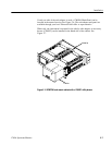
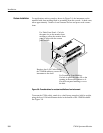
The 70 MHz tuner assembly (A5) is contained in a rigidly mounted shield.
Control signals and the --11.8 V supply are brought into this shielded tuner
through feedthrough capacitors.
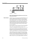
IF Amplifier
Diagram 2
This diagram shows the L--Band and 70 MHz inputs to the various conversion
stages. It also shows the Local Oscillator/Tripler circuitry, Mixers, Amplifiers,
IF filters, and Log Detector output.
Both Local Oscillator (LO) signals are derived from a single crystal, whose
operating frequency is 119.8 MHz. The crystal is a 5
th
overtone type in a Butler
oscillator configuration using Q13. Q11 buffers the oscillator and drives a 3 dB
isolation pad on the LO input of Double Balanced Mixer (DBM) U25. Q12 is a
cascode stage driving a tank circuit at the 3
rd
harmonic (359.4 MHz). The tank
circuit is tapped down to drive a three-section helical resonator, FL1, tuned to
359.4 MHz. The output from FL1 is coupled into DBM U28.
70 MHz Local Oscillator
2
nd
Local Oscillator