


Theory of Operation
1705A Spectrum Monitor
4-15
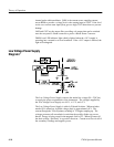
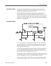
The input line voltage is filtered by the rear-panel connector to reduce the
electrical noise conducted into or out of the instrument. R89 limits the initial
charging current through the rectifier diodes and C54.
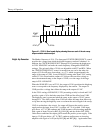
CR21, CR22, CR23, and CR24 form a bridge rectifier. C54 filters the 110 to
350 Vdc rectifier output. L4 filters the switching noise produced by the
switcher. R102 reduces the circulating current in the parallel circuit consisting of
L4 and C44. DS4, R93, and R94 form a line voltage indicator. R91 and R92
charge C42. C 42 provides power to U5 until the primary housekeeping winding
provides power through CR17.
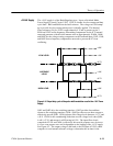
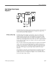
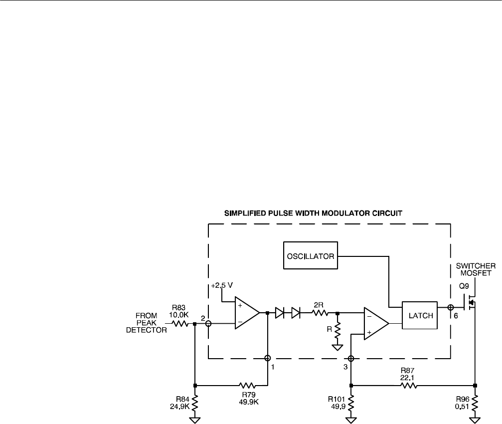
U5 is a current-mode pulse width modulator (PWM). A current-mode PWM
uses two feedback loops. The inner current-feedback loop directly controls the
switcher mosfet peak current. The outer voltage-feedback loop programs the
inner loop peak current trip point.
U5 pin 2 is the inverting input of an internal op-amp. The non-inverting input is
set to 2.5 V by an internal voltage reference. Current from the peak detector
flows through R83 and R79. R84 provides a 100 A offset. The voltage at U5
pin1willvaryinordertomaintainU5pin2at2.5V.
The voltage at U5 pin 1 is modified by an internal circuit and sets the trip point
of the internal comparator. U5 pin 3 is the external input to the comparator. R88
and C52, connected to U5 pin 4, set the internal oscillator to 80 kHz.
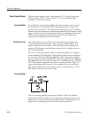
The circuit works as follows: The oscillator resets the latch and U5 pin 6 goes
high, turning the switcher mosfet on. The current through the switcher mosfet
Line Rectifier and Filter
Pulse Width Modulator