


Maintenance
1705A Spectrum Monitor
6-9
Refer to the Replaceable Electrical Parts list for a complete description of each
component.
NOTE. Check the Change Information section at the rear of the manual for
corrections and modifications to the instrument and the manual.
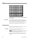
Look up Charts
. Each schematic diagram is assigned an alphanumeric grid and
a look up chart which lists the grid location of components on that schematic.
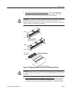
Circuit Board Illustrations
. Electrical components, connectors, and test points
are identified on circuit board illustrations, which are located on the back of a
preceding schematic diagram.
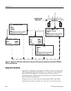
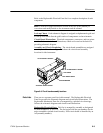
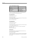
Assembly and Circuit Numbering
. The circuit board assemblies are assigned
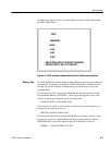
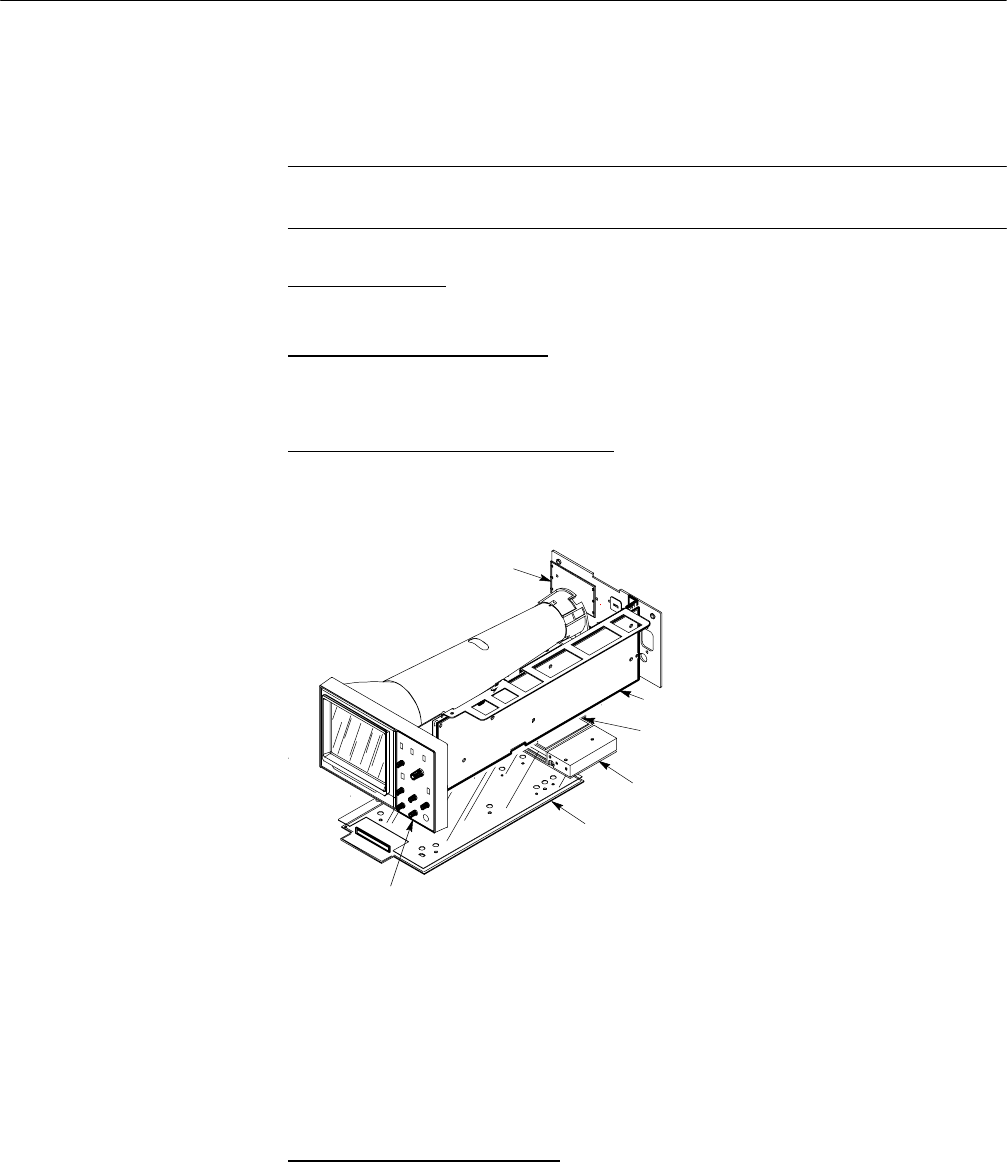
assembly or “A” numbers. Figure 6-6 shows the circuit board assembly
locations for this instrument.
A2 FRONT PANEL BOARD
A3 MAIN BOARD
A1 POWER SUPPLY BOARD
A4 18V SUPPLY BOARD
A5 70MHZ TUNER
A6 TUNER
Figure 6-6: Circuit board assembly locations
There are two separate parts lists in this manual. The Replaceable Electrical
Parts list precedes the schematic diagrams and circuit board illustrations. The
Replaceable Mechanical Parts list, accompanied by exploded view drawings,
follows the schematic diagrams and circuit board illustrations.
Replaceable Electrical Parts
. This list is arranged by assembly as designated
in ANSI Standard Y32.16--1975. The list begins with the part numbers for the
major assemblies (etched circuit boards). Each circuit board is identified by an
A# (assembly number).
Parts Lists