


Theory of Operation
1705A Spectrum Monitor
4-11
Microprocessor
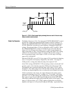
Diagram 5
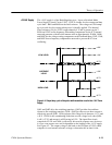
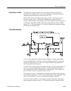
The 1705A is a microprocessor-controlled instrument. Circuitry on Diagram 5
shows the microprocessor, the front-panel LED drive, the crt readout drive, the
graticule light circuit, and the trace rotation circuit.
The processor (U2) is an 8-bit, 3-port microprocessor running at 12 MHz. U8 is
the lower order address de-multiplexer for the Program PROM U9. U9 is a 64K
UV Erasable CMOS PROM. R5 is the bus termination assuring TTL levels (0
=0 V, 1 = 5 V). Output enable for the PROM is the PSEN output from the
microprocessor (U2, pin 29). The lower-order addresses from the processor
(AD0 -- AD7), which are de-multiplexed by U8, are from Port 0; the higher-order
addresses (AD8 -- AD12) are from Port 2. The higher-order addresses are not
multiplexed.
Port 1 is a multifunction input/output port. Lines 0 through 4 are used to poll the
front-panel push-button switches (momentary ground closures) to set up the
measurement program. Line 6 outputs the clock (U2, pin 7) that is used by the
Readout DAC and the NVRAM (Non-Volatile Random Access Memory).
Line 5 is the data transfer (U2, pin 6) for the NVRAM, U4. The Readout Enable
(/RO--EN) that turns on the crt readout is output through Line 7 (U2, pin 8). The
Center Frequency Readout data from U1, the readout ADC, is input through
Line 5 also (U2, pin 6).
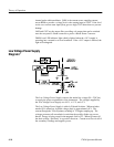
U1 is an A-to-D Converter (ADC), with successive approximation register. It is
used to convert the analog voltage level from the front--panel CENTER
FREQUENCY control to a digital signal for the microprocessor and the Readout
Digital-to-Analog Converter (DAC). R4 is the calibration adjustment to ensure
correct readout.
U4 is the NVRAM that stores the instrument condition when power is turned off
or lost, to ensure that the instrument will come back up in the correct operating
condition. The power down detection circuit consists of a comparator, U11, and
a +5 volt regulator, U3. U3 input voltage is from the +15 volt supply. C5
charges up high enough to allow U3 to continue to power U11 so that it can store
needed data during the power-down sequence. U11 monitors the +5 volt supply
on pin 2. Pin 3 is set to approximately 2.5 volts and has a large capacitor, C13,
to provide a slow decay. Under normal conditions, pin 2 is slightly higher than
pin 3, keeping the output (pin 7) high. When instrument power starts to go
down, pin 2 goes below pin 3, which forces the output (pin 7) low to enable the
/STO input to U4. When /STO goes low, the current conditions, as input from
the microprocessor D -Out output, are stored in the U4 Non-Volatile RAM.
Microprocessor