


Checks and Adjustments
1705A Spectrum Monitor
5-15
s. CHECK -- that the readout still reads 1000, ±10.
t. Set SPAN/DIV to 1 MHz.
u. CHECK -- that the marker is on screen. Position the marker under the
caret with the CENTER FREQUENCY control.
v. CHECK -- that the readout still reads 1000, ±10.
w. Set SPAN/DIV to 100 kHz.
x. CHECK -- that the marker is on screen.
y. Repeat steps m. through x., substituting 1700 MHz.
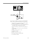
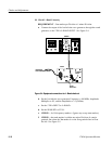
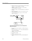
12. Check L--Band Gain and Flatness
REQUIREMENT -- Flatness: ±5dB(± from center (1400 MHz)).
Relative Amplitude Accuracy ±3 dB/100 MHz. (Typically ±1 dB/100
MHz.)
a. Set SPAN/DIV to FULL.
b. Set the 1705A SWEEP SPEED fully counterclockwise.
c. Set the UHF signal generator Frequency to 1400 MHz and Amplitude to
--30 dBm. Position the tip of the marker to the --10 graticule reference
line (vertical scale).
d. Change the UHF signal generator Frequency to 950 MHz.
e. CHECK -- that the marker is on the same crt center line (vertically),
±0.5 Division.
f. Change the UHF signal generator Frequency to 1700 MHz.
g. CHECK -- that the marker is on the same crt line (vertically), ±0.5
Division.
h. Set the UHF signal generator Frequency to 1400 MHz.
i. Position tip of marker to crt center.
j. CHECK -- that the marker tip is on the --10 graticule reference line,
±0.5 Division. Note: Make sure that the baseline is on the --70
graticule reference line.
13. Check Positioning Range
REQUIREMENT -- Vertical: + and --3 Divisions, Horizontal: + and --2
Divisions.