


Checks and Adjustments
1705A Spectrum Monitor
5-21
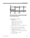
b. Exit the DAC test pattern by first pressing the INPUT button to display
the TEST menu.
c. Press either SPAN/DIV button to move the cursor to EXIT, then press
the INPUT button twice to return to a normal display.
A3 MAIN BOARD
(Refer to Figure 5-7 for adjustment locations)
5. Adjust On-Board Regulated Power Supplies
a. Connect the voltmeter ground lead to the rear-panel LNB POWER
switch ground lug, and the active lead to the --11.8 V test point (W8).
SeeFigure5-7.
b. ADJUST -- R 9 9 ( -- 1 1 . 8 V A D J ) f o r -- 1 1 . 8 V ( -- 1 1 . 7 8 t o -- 1 1 . 8 2 V ) .
c. Connect the voltmeter active lead to the +11.8 V test point (W9). See
Figure 5-7.
d. ADJUST -- R111 (+11.8 V ADJ) for +11.8 V (+11.78 to +11.82 V).
6. Adjust Horizontal Gain
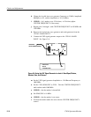
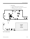
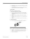
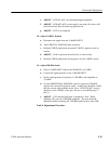
a. Connect a shorting strap between W11 and W12. See Figure 5-9.
W11
W12
SHORTING
STRAP
Figure 5-9: Location of the shorting strap used when adjusting sweep length
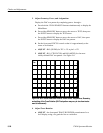
b. ADJUST -- R168 (HORIZ GAIN) for a sweep length of 10 major
Divisions. Use the --60 horizontal graticule line as the reference.
c. Remove the shorting strap.