


Theory of Operation
4-6
1705A Spectrum Monitor
DBM U28 is driven by the L--Band Tuner output at 489.9 MHz through a
LPF/Notch filter consisting of L11, L12, and series resonant circuit C69 and
W13. W13 is a shorted length of 50Ω coax forming a high-Q inductor. This
provides a narrow notch at 590 MHz to eliminate a spurious output from the
L--Band Tuner.
The output from DBM U28 drives U31 which provides about 8 dB gain to
compensate for the mixer loss and optimize the system dynamic range. This
signal is then combined with the 70 MHz tuner output with 3 dB combiner T1.
The band-pass filter, FL2, is a three-section helical resonator with about 8 MHz
bandwidth.
U25 is a double balanced mixer that converts the 130.5 MHz 2
nd
IF frequency to
the 10.7 MHz 3
rd
IF frequency. The LO frequency (119.8 MHz) is below the
2
nd
IF frequency by the 3
rd
IF frequency. J6 is a test jumper that can be lifted to
evaluate prior circuitry or to insert a signal at the 3
rd
IF frequency to trouble-
shoot the circuits that follow.
The 2
nd
IF Amplifier, U22, has a gain of 20 dB. U22 requires a 6 V Vcc; VR3
and R136 are used to derive the voltage from the +11.8 V supply. C31 and C32
are decoupling capacitors. The output signal level is --20 dBm maximum. J5 is
another test jumper that can be used to access prior circuits or insert a signal at
the 2
nd
IF frequency.
The 10.7 MHz 2
nd
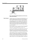
IF signal passes through the 300 kHz Resolution filter or a
combination of the 10 kHz and the 300 kHz Resolution filters. The switching of
filters is accomplished by a combination of a control signal (/10KHZ) from the
microprocessor (Diagram 5) and a switching network consisting of U23D, E, and
F, Q9, and Q10, and switching diodes (CR22, 23, 25, 26, 27, 28, 29, and 30).
When the control line is low, the signal path is through the 10 kHz filter. The
300 kHz filter is always in the circuit. Q10, CR22, and CR30 turn on to enable
the 10 kHz filter; Q9, CR23, and CR28 turn off to switch out the bypass line.
When the control line goes high, Q10 turns off to turn off CR22 and CR30; Q9,
CR23, and CR28 turn on to shunt the 10 kHz filter and provide 300 kHz
resolution. R175, the 300 kHz Gain adjustment, is set to match the loss of the
10 kHz filter. J10 is another test jumper provided to access prior circuits or
insert a signal directly into the Log Detector.
The input to the Log Detector, U32, is amplified by U29 and pre-shaped by FL3
and FL4, a 300 kHz Resolution filter, and then ac coupled to U32. When the
10 kHz filter is selected, the signal is filtered by the 10 kHz filter and then
applied to the Log Detector. The output current from the Log Detector is
processed by Q24 and Q25 to the 15 kHz low-pass filter at U27 pin 3 (Dia-
gram 4). The filter output then drives the Vertical Deflection Amplifier.
Input Filter, Mixer, and IF
Amplifier
Resolution Filter and Log
Detector