


Maintenance
1705A Spectrum Monitor
6-17
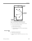
Connect the oscilloscope probe to the anode of CR5 and the probe ground to
TP1. The signal should be a clipped sine wave of +75 to +200 V p-p.
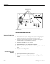
High Voltage Oscillator Check
Connect the oscilloscope probe to T1 pin 3 (Q6 collector) and the probe ground
to TP1. Power up the supply. The signal should be a +60 V p-p, 22 kHz sine
wave.
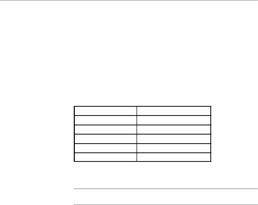
Check the following voltages using the digital multimeter:
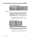
Table 6- 6: High Voltage Oscillator Te st Points
Circuit Location Voltage
T1, pin 4 Approximately +40 V.
T1, pin 13 Less than +2 V.
U2, pin 2 Approximately +4.8 V.
U2, pin 6 +4 to +11 V.
CR9, cathode A pproximately +100 V.
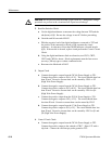
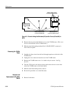
CRT Voltage Check
NOTE. This check requires a high voltage probe having an input resistance of 1
GΩ or more.
Connect the high voltage probe ground to TP1.
Load the Low Volts Supply with the instrument, or with a 20Ω, 2 watt resistor
loading the 5 V supply.
Power up the Power Supply.
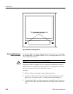
Use the high voltage probe to measure the voltage at the anode of CR4. It
should be approximately --2530 V.
Measure the voltage at the anode end of CR3. It should be 50--150 V more
negative than the reading from the anode of CR4.