


Introduction
1-16
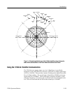
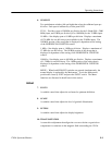
1705A Spectrum Monitor
Tek
REF
--10
--20
--30
--40
--50
--60
--70
L
O
G
+f
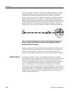
11.73 GHZ
13 5 7 9111315
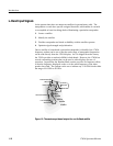
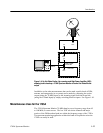
Figure 1-8: Simulation of a 1705A FULL SPAN/DIV display showing six transponders
illuminated
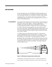
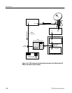
The 70 MHz Input to the spectrum monitor is a bnc connector. It is designed for
use with the IF signal from an up link exciter. Most up link transmitters use an
exciter to drive an Upconverter and High Power Amplifier (HPA), and, in most
cases, the driving signal to the Upconverter is a 70 MHz IF. If the exciter output
is at the up link frequency, a 70 MHz monitoring point is often provided.
Sometimes the coupling of the IF signal between the exciter and Upconverter is a
coaxial link that can be opened and a directional coupler installed for sampling
purposes. See Figure 1-9.
NOTE. The 70 MHz input is rated at --20 dBm maximum, external pads may be
required to meet this operating condition.
Once a directional coupler is installed a whole series of checks can be made,
including presence of the proper carriers and an indication of the modulation
level. More detail can be found in the Tektronix Television booklet “Television
Operational Measurements; Vi deo and RF for NTSC Systems.”
Looking at Exciters with
the 70 MHz Input