


Checks and Adjustments
5-14
1705A Spectrum Monitor
h. Change the leveled sine wave generator Frequency to 5 MHz, Amplitude
Multiplier to X1, and the Amplitude to 3.0 (14 dBm).
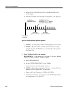
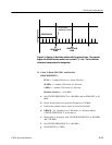
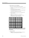
i. CHECK -- for 1 marker every 5 Divisions, ±1 Division (adjust
CENTER FREQUENCY, if necessary).
j. Repeat parts f. through i. with CENTER FREQUENCY at 950 MHz and
1700 MHz.
k. Remove the leveled sine wave generator and comb generator from the
1705A L--BAND INPUT.
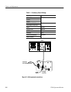
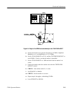
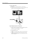
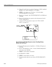
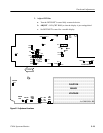
l. Connect the UHF signal generator output to the 1705A L--BAND
INPUT. See Figure 5--6.
VARIABLE
AUTOTRANSFORMER
L--BAND
INPUT
UHF SINE
WAVE
GENERATOR
1705A
Figure 5-6: Using the UHF Signal Generator to check L- Band Span/Division,
Readout, Gain, and Flatness
m. Set the UHF signal generator Amplitude to --50 dBm and Frequency to
1000 MHz.
n. Set the 1705A SPAN/DIV to FULL. Dial the CENTER FREQUENCY
until readout reads 1000 MHz.
o. CHECK -- that the marker is intensified.
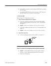
p. Set SPAN/DIV to 10 MHz.
q. CHECK -- that the marker is on screen.
r. Position the marker under the caret with the CENTER FREQUENCY
control.