


Theory of Operation
1705A Spectrum Monitor
4-13
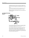
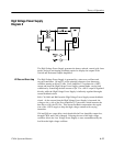
The +18 V supply is of the Buck-Regulator type. It uses a Switched Mode
Power Supply Control Circuit, U583. Q783 is a buffer for slow startup and duty
cycle limit. R681 and R680 are the limit resistors. The voltage on C684 ramps
up to provide for slow startup when power is initially applied. The Internal
Zener reference (V
Z
) for U583 is approximately 8 V and is present on pin 2.
R586 and C583 are the frequency determining components for the IC’s internal
sawtooth generator, which in this instance runs at approximately 50 kHz. R686
and R685 are the voltage setting components on the feedback input; C683, C684,
and R682 form a frequency compensation network to prevent the IC from
oscillating.
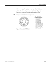
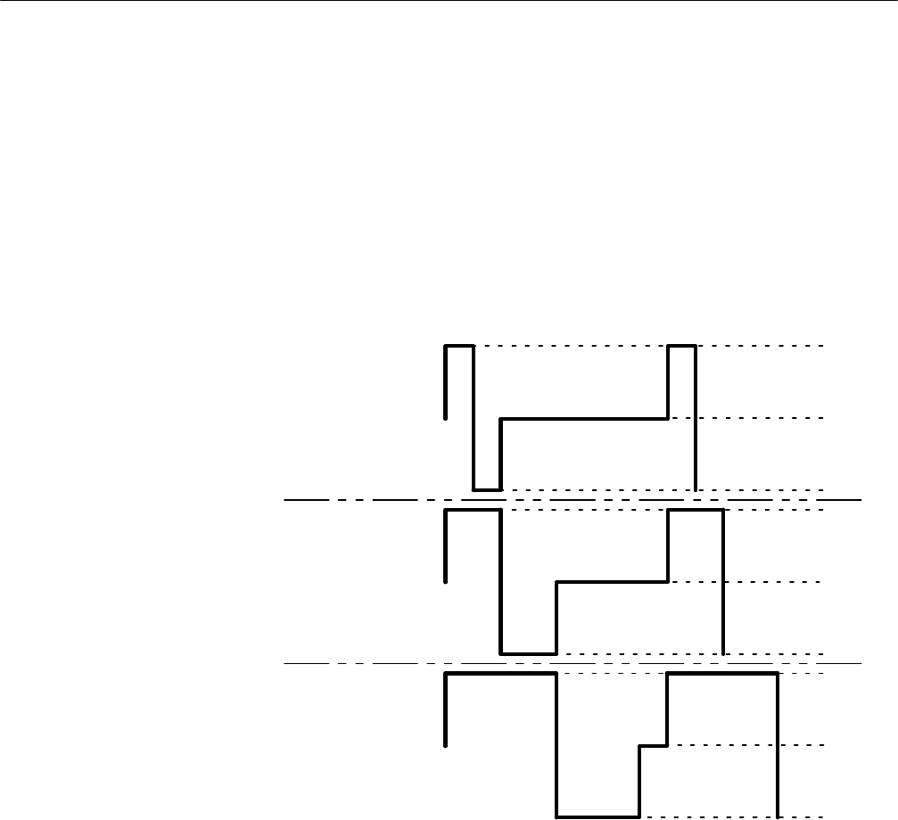
+40V
+40V
+40V
+18V
+18V
+18V
--0.7V
--0.7V
--0.7V
LOW LOAD
AV ERAGE
LOAD
HIGH LOAD
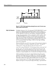
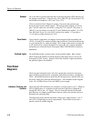
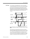
Figure 4-2: Output duty cycle of the pulse width modulator used in the +18 V Power
Supply
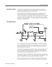
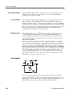
Q481 and Q482 drive the switching transistor. Q482 provides forward base
current to the switching transistor, Q596. Q483 provides reverse base current to
effectively turn off Q596. Q596 operates with voltage levels between --0.7 V and
+40 V. CR594 is the commutating diode that sets the voltage level when Q596
is off (--.07 V) and current is still flowing in L591. The input filter circuit,
composed of L591 and C690, is effectively driven with a square wave; however
it is not a true square wave and is dependent on the loading of the +18 V supply.
See Figure 4-2. The output voltage is fed back to the FB input of U583, which
compares it to an internal reference voltage to determine the on time for the
+18 Volt Supply