


Theory of Operation
4-2
1705A Spectrum Monitor
driven with a pre-corrected sweep ramp. Pre-correction is required to make up
for the inherent VCO nonlinearity.
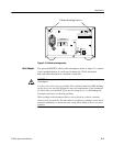
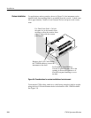
A +18 V supply is connected to the L--BAND input connector so that it can be
used to power a Block Down Converter (usually at the antenna). The supply can
be switched on and off by a recessed slide switch on the rear panel. The voltage
is generated on a separate circuit board that is mounted inside the 1705A rear
panel.
The L--Band Tuner output passes through a 1
st
IF filter which contains a notch at
590 MHz to eliminate a spurious mixing product. It is then mixed with an L.O.
of 359.4 MHz to produce a 2
nd
IF output at 130.5 MHz. This output is
amplified by an 8 dB gain MMIC and is combined with the 70 MHz tuner
output.
The 70 MHz input consists of a 7-pole, 120 MHz, bandwidth low-pass filter; a
VCO (which, like the L--Band VCO, is driven by a pre-corrected sweep ramp); a
mixer; and a 20 dB amplifier. The 70 MHz input circuits also output a 136 MHz
1
st
IF with a gain of 0 dB ±3dB.
The 136 MHz 2
nd
IF is converted a third time to produce a 3
rd
IF frequency of
10.7 MHz. The crystal-controlled Local Oscillator operates at 119.8 MHz to
provide the 10.7 conversion. The oscillator’s output is tripled to 359.4 MHz to
provide the 130.5 MHz conversion for the L--Band Tuner output. A three-sec-
tion helical resonator is used for the 130.5 MHz IF filter.
An additional band-pass crystal filter, centered at 10.7 kHz, with a 10 kHz
bandwidth, can be added by front-panel selection, to provide narrow resolution.
The 300 kHz bandwidth filter is always in the circuit regardless of the front-pa-
nel RESOLUTION selection. Maximum bandwidth of the 1705A is 300 kHz.
The resolution filters drive a FSK receiver IC. Only the meter output of this IC
is used to provide a voltage proportional to the log of the input power. This
drives a selectable video filter and the Vertical Deflection Amplifier.
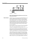
The output of the Ramp Generator drives the Horizontal Deflection Amplifier
(Diagram 4), Gain Control (SPAN/DIV), and the Marker Generator. The Ramp
Generator free runs with its repetition rate controlled by the front-panel SWEEP
SPEED control. The amplitude of the ramp remains constant.
The Gain Control, which provides the ramp that is eventually used to drive the
VCOs, consists of an operational amplifier with selectable input resistances. The
resistance selected is dependent upon the SPAN/DIV setting selected from the
front panel. The output ramp from the Gain Control circuit drives the Sweep
Shapers.
The CENTER FREQUENCY control provides an offset to the sweep ramps in
all SPAN/DIV settings except FULL. In the FULL S PAN/DIV setting, a
IF Amplifier Circuits
(Diagram 2)
Sweep Generator Circuits
(Diagram 3)
Test Equipment Depot - 800.517.8431 - 99 Washington Street Melrose, MA 02176 - FAX 781.665.0780 - TestEquipmentDepot.com