


Theory of Operation
1705A Spectrum Monitor
4-19
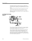
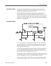
Q5 is a current amplifier feeding the output stage. Q3 and Q4 form a push-pull
output stage. Q3 acts as a 2.7 mA constant current pull-up, while Q4 is the
pull-down transistor. C6 speeds up the amplifier by coupling ac signals to the
base of Q3. CR2 and R41 protect the amplifier during crt arcing.
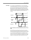
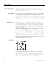
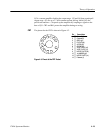
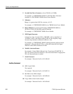
The pinout for the CRT is shown in Figure 4-3.
Pin Description
1 Filament (f)
2 Cathode (k)
3 GRID (g1)
4 FOCUS (g3)
5 ASTIG (g4)
6 GEOM (g5)
7 VERT PLATE (y2)
9 VERT PLATE (y1)
11 HORIZ PLATE (x2)
12 1st ANODE (g2)
13 HORIZ PLATE (x1)
14 Filament (f)
14
13
12
11
9
7
6
54
3
2
1
Figure 4-3: Pinout of the CRT Socket
CRT