


Checks and Adjustments
5-12
1705A Spectrum Monitor
10. Check L--Band Linearity
REQUIREMENT -- One marker per Division ±1 minor Division.
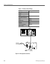
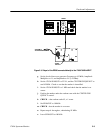
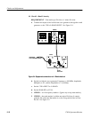
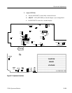
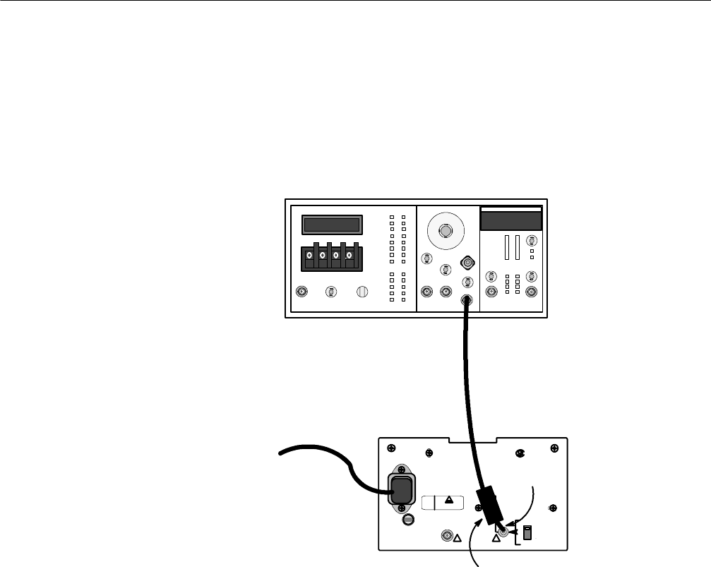
a. Connect the output of the leveled sine wave generator, through the comb
generator, to the 1705A L--BAND INPUT. See Figure 5-4.
SG503
Comb
Generator
VARIABLE
AUTOTRANSFORMER
L--BAND
INPUT
1705A
Figure 5-4: Equipment connections for L- Band checkout
b. Set the leveled sine wave generator Frequency to 100 MHz, Amplitude
Multiplier to X1, and the Amplitude to 1.5 (8 dBm).
c. Set the 1705A INPUT to L--BAND.
d. Set the SPAN/DIV to FULL.
e. CHECK -- for 10 frequency markers. (Ignore any sweep start marker.)
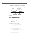
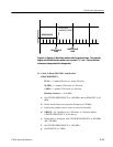
f. CHECK – that each marker is within one minor Division of a major
graticule line when the 2
nd
marker is on the first graticule line in from
theleft. SeeFigure5-5.