


Checks and Adjustments
1705A Spectrum Monitor
5-7
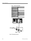
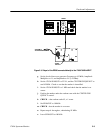
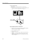
c. Connect the leveled sine wave generator output to the comb generator.
Connect the comb generator output to the 1705A rear-panel 70 MHz
INPUT. See Figure 5-1.
2. Check Power Supply Operation
REQUIREMENT — Check ac input range, 90 -- 250 V.
a. Set the leveled sine wave generator Frequency to 5.0 MHz, the
Amplitude Multiplier to X1, and the Amplitude to 4.0 (+16 dBm).
b. Adjust the controls for a usable display.
c. Vary the autotransformer from low-line to high-line voltage (90 - 132 V
for 110 V, or 180 - 250 V for 220 V operation).
d. CHECK -- for stable operation over the prescribed voltage range. (Note:
If the LNB POWER is on and in use, the requirement is derated to 100 --
132 V or 200 -- 250 V.)
e. Return the autotransformer to the local nominal mains voltage.
3. Check LNB Power Supply
REQUIREMENT — +18 Vdc ±5%.
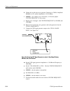
a. Connect DVM leads between the center conductor of the L--BAND
INPUT connector and ground.
b. Turn on the LNB POWER switch.
c. CHECK -- that the rear-panel, LNB POWER LED is ON, and that the
DVM reads +18 V ±0.9 V.
d. Temporarily (approximately 2 seconds) short the L--BAND INPUT
connector center conductor to ground.
e. CHECK -- that the red indicator lamp extinguishes and then comes back
on when the short is removed.
f. Turn LNB POWER off.
CAUTION. The LNB POWER switch MUST be turned off for the rest of this
procedure to prevent damage to the generators used in later steps.
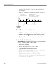
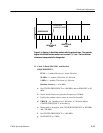
4. Check 70 MHz Linearity
REQUIREMENT — One marker per Division ±1 minor Division.