


Checks and Adjustments
1705A Spectrum Monitor
5-27
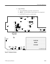
e. ADJUST -- R239 (IF AGC) for maximum signal amplitude.
f. ADJUST -- R240 (RF AGC) so the signal is one major Division (±0.5
major Divisions) down from the top graticule line.
g. ADJUST -- R232 to its midpoint.
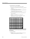
18. Adjust 2 dB/Div Position
a. Disconnect the signal from the L--BAND INPUT.
b. Turn VERTICAL POSITION fully clockwise.
c. Hold the VIDEO push button down until 2 dB/Div appears on the crt
readout.
d. ADJUST -- R140 to position the noise floor to center screen.
e. Hold the VIDEO push button down again to exit the 2 dB/Div mode.
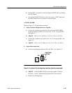
19. Adjust 590 MHz Notch
a. Select L--BAND INPUT and set the SPAN/DIV to 10 MHz.
b. Connect the signal generator to the L--BAND INPUT.
c. Set the signal generator Frequency to 1200 MHz, and Amplitude to
--20 dBm.
d. Use the HORIZONTAL P OSITION control to place the 1200 MHz
signal at the extreme left graticule mark. A small spur should be visible
near the extreme right graticule mark. Note: R240, RF AGC, may be
adjusted to ease visibility of the spur. Be sure to reset R240 (step 17
part f.).
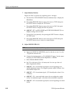
e. ADJUST -- C69 carefully until spur is minimized. Note: While
adjusting C69, note the 1200 MHz amplitude. The spur should be
minimized without reducing the 1200 MHz spike by more than 2 dB.
End of Adjustment Procedure