


Checks and Adjustments
5-18
1705A Spectrum Monitor
15. Adjust Span/Div Magnifier Range (R38 and R37)
16. Adjust Intensified Zone Range (R61 and R36)
17. Adjust Vertical Gain (R176, R239, R240, and R232)
18. Adjust 2 dB/Div Position (R140)
19. Adjust 590 MHz Notch (C69)
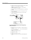
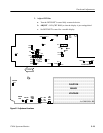
Figure 5-7 shows the 1705A Spectrum Monitor internal adjustment locations.
PRELIMINARY SETUP
Connect the 1705A ac power cord to the variable autotransformer. Turn the
1705A power on. Set the front-panel controls to start this procedure as
showninTable5--2.
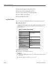
Table 5- 2: Preliminary Control Settings
POWER ON
INTENSITY Set to Preference
FOCUS
SCALE
VERTICAL POSITION Set later
HORIZONTAL POSITION
INPUT 70 MHz
RESOLUTION 300 kHz
VIDEO ON
SPAN/DIV FULL
CENTER FREQUENCY anywhere
SWEEP SPEED
y
A1 POWER SUPPLY BOARD
(Refer to Figure 5-7 for adjustment locations.)
1. Adjust +5 V
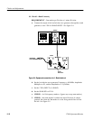
a. Connect the DMM negative lead to TP1 (GND) and the positive lead to
W1 (+5V).
b. ADJUST -- R99 (+5V ADJ) for +5.0 V ᐔ0.5V.
Long Form Procedure