


Theory of Operation
4-4
1705A Spectrum Monitor
regulated to become the + and --11.8 V supplies on the Main circuit board
(regulator circuits are on Diagram 4).
The Power Supply schematic also contains the 11.8 V Post Regulators, whose
outputs are used by most of the circuits on the Main circuit board. The Post
Regulators do not appear on the block diagram.
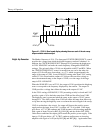
The unblanking signal from the Z--Axis Control drives the Z--Axis Amplifier.
The Focus Amplifier, controlled by the front-panel control, provides a voltage to
the crt focus ring. The crt is of the Post Acceleration type, which requires a
relatively high potential difference between the cathode and post anode. The
boost in 2
nd
anode voltage is provided by an encapsulated 4X Multiplier.
The High Voltage supply also provides the +100 V, required by the Horizontal
Deflection Amplifier (Diagram 4), to drive the crt horizontal deflection plates.
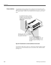
RF Input
Diagram 1
This diagram has both RF inputs for the Spectrum Monitor. The L--Band and
70 MHz inputs are both off-board subassemblies. The 70 MHz input consists of
discrete components on a small circuit board that is totally shielded. The
L--Band Tuner is also self contained, totally shielded, and contains no user-ser-
viceable parts.
The L--Band signal (900 -- 1750 MHz) is input directly to a tuner subassembly
that contains the Tuned RF Amplifier, mixer, and Voltage Controlled Oscillator
(VCO) required to produce the first Intermediate Frequency (IF) of 489.9 MHz.
The 489.9 MHz 1
st
IF signal is cabled to the Main board.
The tuner subassembly is powered by the +11.8 volts, which is controlled by the
Input Switching. (The +11.8 V to the L--Band Tuner is disabled when the
70 MHz input is selected.) In addition, the Block Down Converter +18 V supply
(from Diagram 5) is fed to the tuner for output on its F-type connector. A
recessed, rear-panel slide switch connects the +18 V supply to the L--Band Tuner.
A pre-corrected ramp (from Diagram 3) to drive the VCO is also supplied to the
tuner subassembly.
The /LBAND control line, from the microprocessor, is low when the L--Band is
selected. When /LBAND goes high (indicating that the 70 MHz input has been
selected) Q31 turns on and Q30 turns off, causing Q32 to turn off and disconnect
the +11.8 V from the tuner.
The input to the 70 MHz tuner has a 75Ω, 10 dB pad, which allows it to accept
signals up to --20 dBm. The 70 MHz signal (45 -- 100 MHz) is preconditioned
High Voltage (Diagram 8)
L- Band Input
70 MHz Input