


Operating Instructions
2-18
1705A Spectrum Monitor
2. Stabilize the vehicle in a location where there will be a clear path between
the antenna and the satellite. The vehicle should be reasonably level to
facilitate antenna and polarization adjustment.
3. Point the antenna in the expected direction of the satellite. Note that
compass readings may not be accurate in the presence of vehicles or
structures. Several readings, at nearby locations, should be taken to
determine any unusual effects. Appropriate correction for magnetic variation
must be made when a magnetic compass is used. The locating tables
indicate true north.
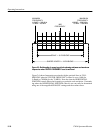
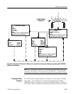
4. If the antenna azimuth and elevation are remotely adjusted, the TEKTRO-
NIX 1705A may be permanently connected to the splitter feeding the
L--Band downlink signal from the outdoor Low Noise Block Converter
(LNB) to the indoor receiver. If the antenna is to be adjusted manually, a
portable ac or battery-powered 1705A may be connected directly to the LNB
at the antenna, in which case the spectrum monitor can be used to power the
LNB.
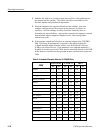
Table 2- 3: Azimuth / Elevation Table for 21 CONUS Cities
C
I
T
Y
SATCOM K2 G--STAR II SBS--3
CITY
AZ EL
AZ EL AZ EL
Atlanta 175˚
50˚ 214˚ 45˚ 199˚ 49˚
Boston
195˚ 40˚ 225˚ 31˚ 214˚ 36˚
Chicago
170˚ 41˚ 205˚ 38˚ 190˚ 41˚
Dallas /Ft. Worth
150˚ 47˚ 192˚ 53˚ 172˚ 51˚
Denver
145˚ 38˚ 180˚ 44˚ 165˚ 43˚
Detroit
177˚ 44˚ 212˚ 38˚ 198˚ 42˚
Houston
153˚ 52˚ 199˚ 53˚ 180˚ 55˚
Las Vegas
131˚ 35˚ 163˚ 47˚ 148˚ 43˚
Los Angeles
127˚ 34˚ 158˚ 48˚ 143˚ 43˚
Miami
180˚ 61˚ 227˚ 49˚ 211˚ 55˚
Minneapolis/St Paul
164˚ 37˚ 198˚ 37˚ 184˚ 38˚
Nashville
170˚ 48˚ 209˚ 44˚ 193˚ 47˚
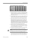
New Orleans 162˚ 54˚ 208˚ 51˚ 190˚ 55˚
New York 191˚ 42˚ 223˚ 33˚ 211˚ 38˚
Philadelphia 189˚ 43˚ 222˚ 34˚ 210˚ 39˚
Phoenix 132˚ 39˚ 168˚ 51˚ 150˚ 47˚