


Maintenance
1705A Spectrum Monitor
6-13
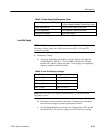
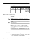
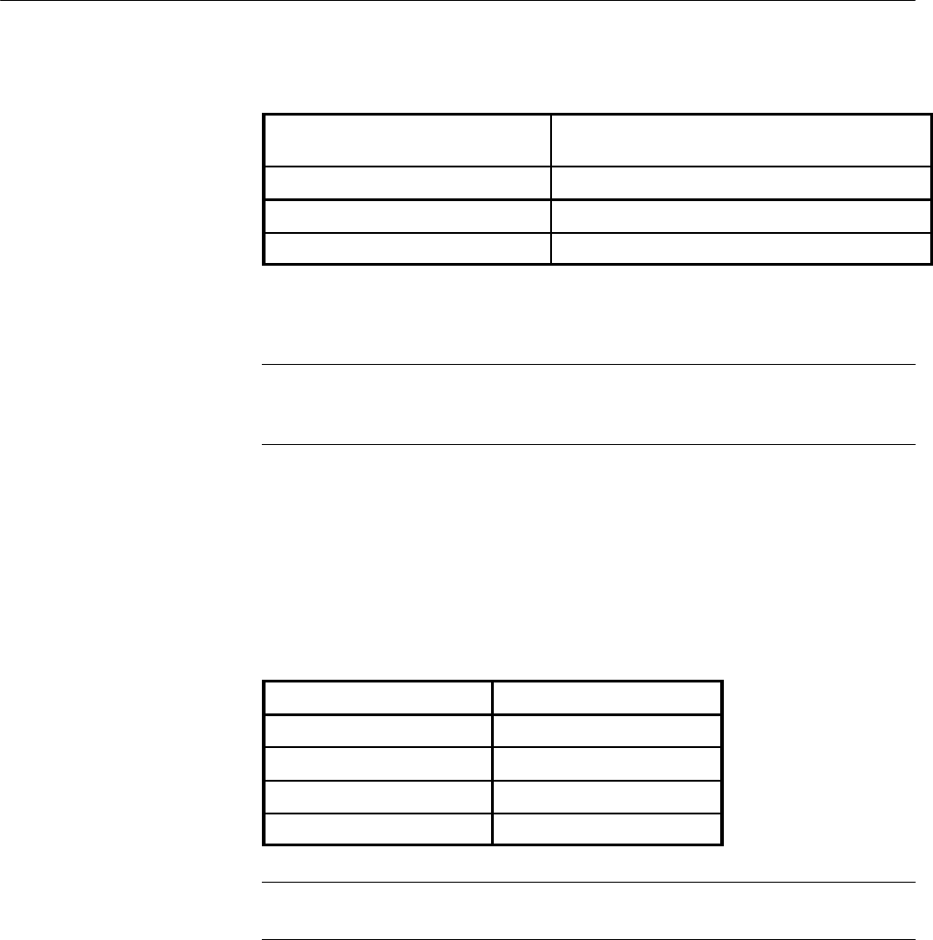
Table 6- 2: Power Supply Fault Symptoms (Cont.)
Power Supply cycles OFF/ON Output Check (Low Vo lts),
or High V oltage Oscillator Check (High Volts)
Does not power up Control Circuit Check (Low Volts)
5 V not regulating Error Amplifier Check (Low Volts)
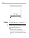
Improper crt display High Volts Supply
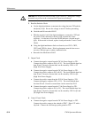
NOTE.A20Ω, 2 watt resistor should be used as a load for the Low Volts Supply.
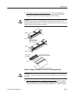
Disconnect J4 and connect the 20Ω resistor between W1 (+5 V) and TP1
(secondary ground).
1. Preliminary Checks
a. A properly functioning and loaded Low Volts Supply will output the
voltages listed in Table 6--3. Use the DMM to measure the voltages
between TP1 and the voltage test points. If the supply is not regulating
properly, continue with the procedure.
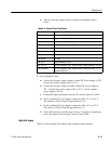
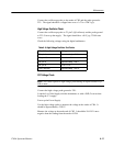
Table 6- 3:
Low Volts Supply Voltages
Test Point
Voltage
W1 -- (+5 V) +4.88to+5.12V
W4 -- (+15 V) +14.0 to +16.0 V
W3 -- (--15 V) --14.0 to --16.0 V
W2 -- (+40 V) +39.0 to +41.0 V
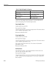
NOTE. The Low Volts Pow er Supply troubleshooting is performed without
applying ac power.
b. Disconnect ac power from the instrument. Disconnect the instrument
from the Power Supply by removing the jumper from J4.
c. Use the digital multimeter to measure the voltage between TP2 and the
tab (drain) of Q9. Be sure the voltage is near 0 V before proceeding.
Low Volts Supply