


Theory of Operation
4-12
1705A Spectrum Monitor
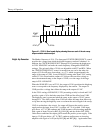
U6 is an 8-bit D-type data latch that drives all the front-panel LEDs and most of
the internal control lines. Chip select for U6 is /WR (U2, pin 16) inverted (U7C)
and ANDed with Address 14 (U2, pin 27) by U7A.
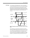
U10 is a dual 8-bit DAC (Digital-to-Analog Converter) that generates the
horizontal and vertical readout signals. The analog current outputs of U10 are
pins 2 and 20, which are converted to voltage by U12 A and B. Chip select is
/WR (U2, pin 16) which is inverted (U7C) and ANDed with Address 7 in U7D.
Line A0 from U8, pin 19, is the DAC A select (low enable). U5 provides a
--5 volt analog voltage reference for U10.
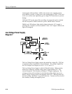
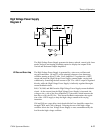
Trace rotation compensates for changes in the magnetic field surrounding the
1705A. Q1 and Q2 are emitter followers that provide the Trace Rotation current
to a coil around the crt, inside the shield. The voltage on the emitter of either Q1
or Q2 will develop a current through R19 to drive the coil. Current amplitude
and polarity are controlled by the front-panel TRACE ROTATION screwdriver
adjustment.
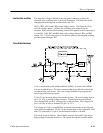
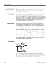
Q3 and Q100 provide a current source for the graticule lights. Base voltage,
which controls the amount of current flowing in the light circuit, is set by the
front-panel SCALE control. Jumper J100 on the Graticule Light board allows
the graticule lights to be disabled.
Front Panel
Diagram 6
The front-panel schematic shows all of the operational controls for the instru-
ment, including potentiometers, momentary push-button switches, and indicator
LEDs. All the push buttons are polled by the microprocessor, and the LEDs are
driven by output ports from the microprocessor. Also included on this diagram
is the +18 volt Block Down Converter (BDC) power supply.
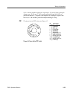
The front-panel LED indicators are returned to a current source (+5 V). When an
LED is lighted, there is a complete circuit from the Light Driver (Diagram 5)
through the LED to the +5 V supply. The five function switches (front-panel
push buttons) are simple ground closures that are read by the microprocessor to
determine the operating mode.
The eight front-panel controls determine voltages (in a range between --11.8 V
and +11.8 V) depending on circuit requirements. Each control works with a
specific circuit on another diagram.
Readout
Trace Rotate
Graticule Lights
Indicators, Controls, and
Switches