


3 - 53
3. SIGNALS AND WIRING
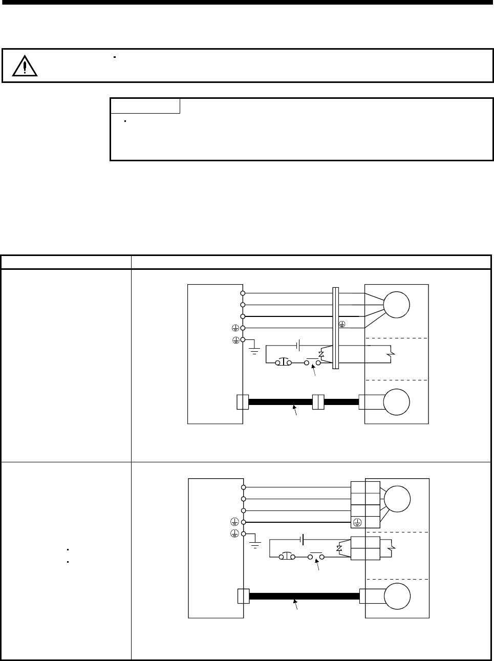
3.8.2 Connection diagram
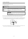
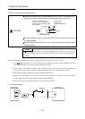
CAUTION
During power-on, do not open or close the motor power line. Otherwise, a
malfunction or faulty may occur.
POINT
For the connection diagram of the MR-J2S-11KA to MR-J2S-22KA, refer
to section 3.13 where the connection diagram is shown together with the
power line circuit.
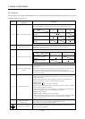
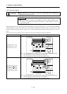
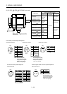
The following table lists wiring methods according to the servo motor types. Use the connection diagram
which conforms to the servo motor used. For cables required for wiring, refer to section 13.2.1. For
encoder cable connection, refer to section 13.1.5. For the signal layouts of the connectors, refer to section
3.8.3.
For the servo motor connector, refer to chapter 3 of the Servo Motor Instruction Manual.
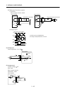
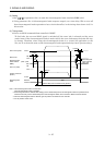
Servo motor Connection diagram
HC-KFS053 (B) to 73 (B)
HC-MFS053 (B) to 73 (B)
HC-UFS13 (B) to 73 (B)
Servo amplifier
(Note 1)
Servo motor
Electromagnetic
brake
24VDC
EMG
(Note 2)
To be shut off when servo-off
or Trouble (ALM)
Encoder cable
CN2
Motor
Encoder
U
V
W
B1
B2
U (Red)
V (White)
W (Black)
(Green)
Note 1. To prevent an electric shock, always connect the protective earth (PE) terminal of the
servo amplifier to the protective earth (PE) of the control box.
2. This circuit applies to the servo motor with electromagnetic brake.
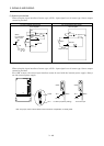
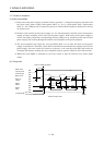
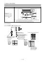
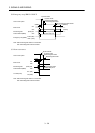
HC-SFS121 (B) to 301 (B)
HC-SFS202 (B)
702 (B)
HC-SFS203 (B)
353 (B)
HC-UFS202 (B) to 502 (B)
HC-RFS353 (B) to 503 (B)
Electromagnetic
brake
(Note 2)
To be shut off when servo-off
or Trouble (ALM)
24VDC
EMG
CN2
U
V
W
U
V
W
B1
B2
Servo amplifier
(Note 1)
Encoder
Encoder cable
Motor
Servo motor
Note 1. To prevent an electric shock, always connect the protective earth (PE) terminal of the
servo amplifier to the protective earth (PE) of the control box.
2. This circuit applies to the servo motor with electromagnetic brake.