


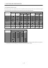
1 - 13
1. FUNCTIONS AND CONFIGURATION
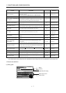
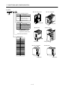
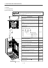
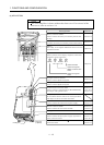
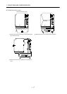
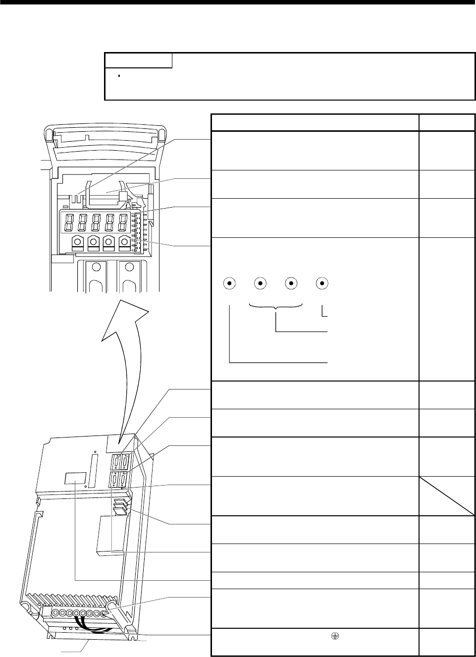
(4) MR-J2S-700A
POINT
The servo amplifier is shown without the front cover. For removal of the
front cover, refer to section 1.7.2.
MODE UP DOWN
SET
Fixed part
(4 places)
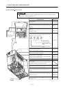
Cooling fan
Encoder connector (CN2)
Used to connect the servo motor encoder.
Charge lamp
Lit to indicate that the main circuit is charged. While
this lamp is lit, do not reconnect the cables.
Main circuit terminal block (TE1)
Used to connect the input power supply, regenerative
option and servo motor.
Control circuit terminal block (TE2)
Used to connect the control circuit power supply.
Protective earth (PE) terminal ( )
Ground terminal.
MODE UP
DOWN SET
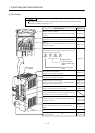
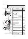
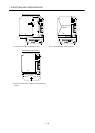
Battery holder
Contains the battery for absolute position data backup.
Communication connector (CN3)
Used to connect a command device (RS-422/RS-232C)
and output analog monitor data.
Battery connector (CON1)
Used to connect the battery for absolute position data
backup.
Reference
Section 15.3
Section 15.3
Chpater 6
Chapter 6
Section 3.3
Section 3.3
Section 3.3
Section 13.1.5
Chapter 14
Section 1.5
Section 3.3
Section 13.1.5
Section 3.7
Section 11.1
Section 13.1.1
Section 3.7
Section 11.1
Section 3.10
Section 11.1
Display
The 5-digit, seven-segment LED shows the servo status
and alarm number.
Operation section
Used to perform status display, diagnostic, alarm and
parameter setting operations.
Used to change the
display or data in each
mode.
I/O signal connector (CN1A)
Used to connect digital I/O signals.
I/O signal connector (CN1B)
Used to connect digital I/O signals.
Rating plate
Name/Application
Used to set data.
Used to change the
mode.