


13 - 44
13. OPTIONS AND AUXILIARY EQUIPMENT
13.2 Auxiliary equipment
Always use the devices indicated in this section or equivalent. To comply with the EN Standard or UL/C-
UL (CSA) Standard, use the products which conform to the corresponding standard.
13.2.1 Recommended wires
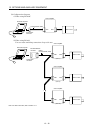
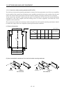
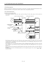
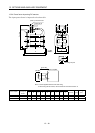
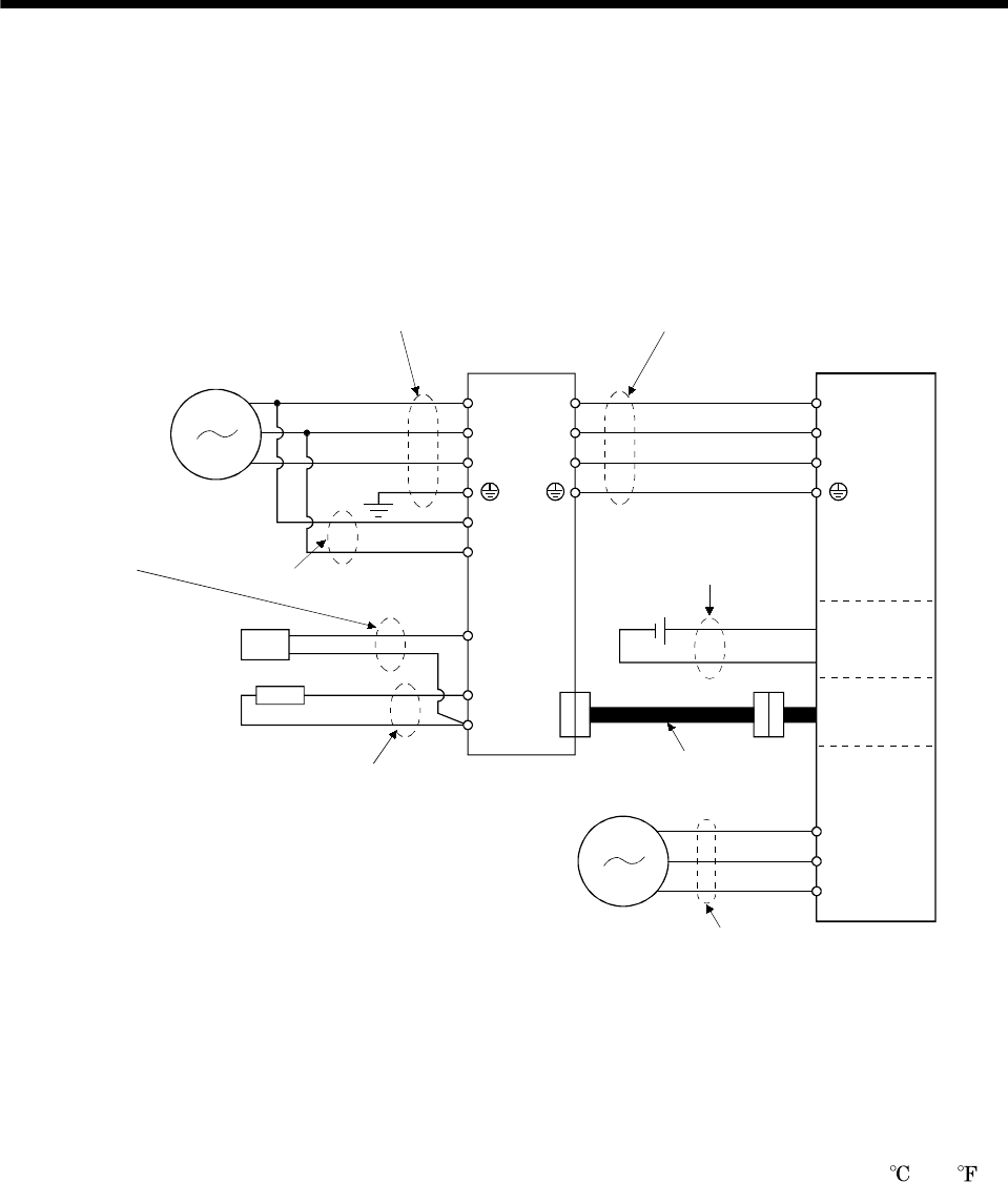
(1) Wires for power supply wiring
The following diagram shows the wires used for wiring. Use the wires given in this section or
equivalent.
C
P
U
V
W
L
11
L
21
B1
B2
U
V
W
L1
L2
L
3
Motor
N
1) Main circuit power supply lead
Power supply
Servo amplifier
3) Motor power supply lead
Servo motor
Electro-
magnetic
brake
Encoder
Encoder cable
(refer to section 13.1.5)
4) Regenerative option lead
5) Electromagnetic
brake lead
2) Control power supply lead
Regenerative option
Cooling fan
BU
BV
BW
Cooling fan lead
Power supply
6) Power regeneration
converter lead
Power regeneration
converter
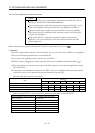
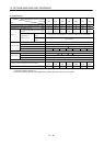
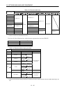
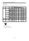
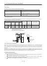
The following table lists wire sizes. The wires used assume that they are 600V vinyl wires and the
wiring distance is 30m(98.4ft) max. If the wiring distance is over 30m(98.4ft), choose the wire size in
consideration of voltage drop.
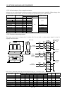
The alphabets (a, b, c) in the table correspond to the crimping terminals (Table 13.2) used to wire the
servo amplifier. For connection with the terminal block TE2 of the MR-J2S-100A or less, refer to
section 3.11.
The servo motor side connection method depends on the type and capacity of the servo motor. Refer to
section 3.8.
To comply with the UL/C-UL (CSA) Standard, use UL-recognized copper wires rated at 60
(140 ) or
more for wiring.