


3 - 54
3. SIGNALS AND WIRING
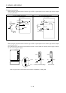
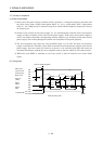
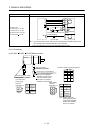
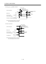
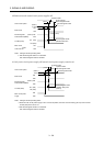
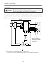
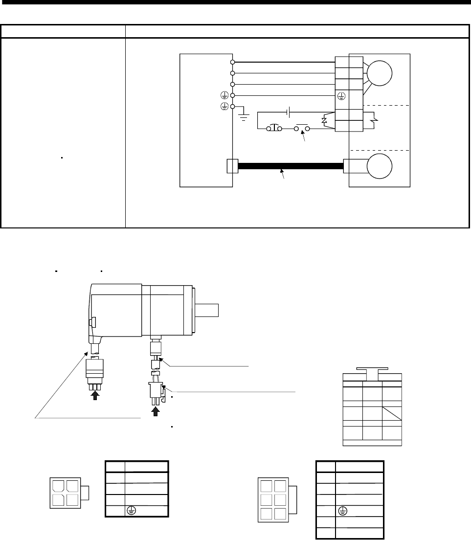
Servo motor Connection diagram
HC-SFS81 (B)
HC-SFS52 (B) to 152 (B)
HC-SFS53 (B) to 153 (B)
HC-RFS103 (B) to 203 (B)
HC-UFS72 (B)
152 (B)
Electromagnetic
brake
(Note 2)
To be shut off when servo-off
or Trouble (ALM)
24VDC
EMG
CN2
U
V
W
U
V
W
B1
B2
Servo amplifier
(Note 1)
Encoder
Encoder cable
Motor
Servo motor
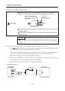
Note 1. To prevent an electric shock, always connect the protective earth (PE) terminal of the
servo amplifier to the protective earth (PE) of the control box.
2. This circuit applies to the servo motor with electromagnetic brake.
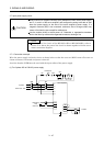
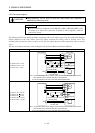
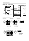
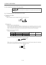
3.8.3 I/O terminals
(1) HC-KFS
HC-MFS HC-UFS3000r/min series
24
13
4
Power supply connector (Molex)
Without electromagnetic brake
5557-04R-210 (receptacle)
5556PBTL (Female terminal)
With electromagnetic brake
5557-06R-210 (receptacle)
5556PBTL (Female terminal)
Encoder cable 0.3m (0.98ft.)
Power supply lead
4-AWG19 0.3m (0.98ft.)
With connector 1-172169-9
(Tyco Electronics)
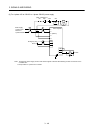
1
2
3
4
1
25
4
36
1
2
3
5
6
Power supply
connector
5557-04R-210
Pin
Signal
(Earth)
U
V
W
Power supply
connector
5557-06R-210
Pin
Signal
(Earth)
U
V
W
MR
123
MRR BAT
MD
456
MDR
P5
789
LG SHD
Encoder connector signal arrangemen
t
B1
B2
(Note)
(Note)
Note. For the motor with
electromagnetic brake,
supply electromagnetic
brake power (24VDC).
There is no polarity.
a
b
View b
View b
View a