


10 - 10
10. TROUBLESHOOTING
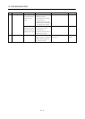
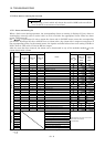
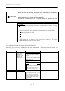
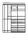
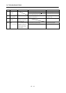
Display Name Definition Cause Action
1. Short occurred in servo amplifier
output phases U, V and W.
Correct the wiring.AL.32 Overcurrent
2. Transistor (IPM) of the servo
amplifier faulty.
Checking method
Alarm (AL.32) occurs if power is
switched on after U,V and W
are disconnected.
Change the servo amplifier.
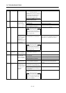
3. Ground fault occurred in servo
amplifier output phases U, V and
W.
Correct the wiring.
Current that flew is
higher than the
permissible current
of the servo
amplifier. (When
the alarm (AL.32)
occurs, switch the
power OFF and
then ON to reset the
alarm. Then, turn
on the servo-on.
When the alarm
(AL.32) still occurs
at the time, the
transistor (IPM
IGBT) of the servo
amplifier may be at
fault. Do not switch
the power OFF/ON
repeatedly; check
the transistor
according to the
cause 2 checking
method.)
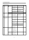
4. External noise caused the
overcurrent detection circuit to
misoperate.
Take noise suppression measures.
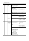
Current higher than
the permissible
current flew in the
regenerative
transistor.
(MR-J2S-500A only)
5. Improper wiring of the
regenerative option.
Wire the regenerative option correctly.
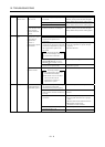
1. Regenerative option is not used. Use the regenerative option.
2. Though the regenerative option is
used, the parameter No. 0 setting
is “ 00
(not used)”.
Make correct setting.
3. Lead of built-in regenerative
resistor or regenerative option is
open or disconnected.
1. Change the lead.
2. Connect correctly.
4. Regenerative transistor faulty. Change the servo amplifier
5. Wire breakage of built-in
regenerative resistor or
regenerative option
1. For wire breakage of built-in
regenerative resistor, change the servo
amplifier.
2. For wire breakage of regenerative
option, change the regenerative option.
6. Capacity of built-in regenerative
resistor or regenerative option is
insufficient.
Add regenerative option or increase
capacity.
7. Power supply voltage high. Check the power supply.
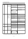
AL.33 Overvoltage Converter bus
voltage exceeded
400VDC.
8. Ground fault occurred in servo
amplifier output phases U, V and
W.
Correct the wiring.
9. The jumper across BUE-SD of the
FR-BU2 brake unit is removed.
Fit the jumper across BUE-SD.
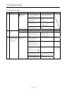
1. Pulse frequency of the command
pulse is too high.
Change the command pulse frequency to a
proper value.
2. Noise entered command pulses. Take action against noise.
AL.35 Command
pulse frequency
error
Input pulse
frequency of the
command pulse is
too high.
3. Command device failure Change the command device.