


3 - 47
3. SIGNALS AND WIRING
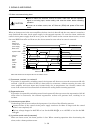
3.7 Input power supply circuit
CAUTION
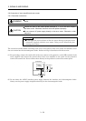
Always connect a magnetic contactor (MC) between the main circuit power supply
and L
1, L2, and L3 of the servo amplifier, and configure the wiring to be able to shut
down the power supply on the side of the servo amplifier’s power supply. If a
magnetic contactor (MC) is not connected, continuous flow of a large current may
cause a fire when the servo amplifier malfunctions.
Use the trouble (ALM) to switch power off. Otherwise, a regenerative transistor
fault or the like may overheat the regenerative resistor, causing a fire.
POINT
For the power line circuit of the MR-J2S-11KA to MR-J2S-22KA, refer to
section 3.13 where the power line circuit is shown together with the servo
motor connection diagram.
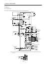
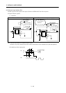
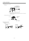
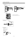
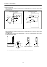
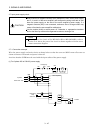
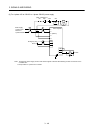
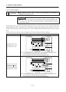
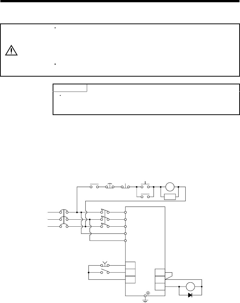
3.7.1 Connection example
Wire the power supply and main circuit as shown below so that the servo-on (SON) turns off as soon as
alarm occurrence is detected and power is shut off.
A no-fuse breaker (NFB) must be used with the input cables of the power supply.
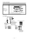
(1) For 3-phase 200 to 230VAC power supply
RA
OFF
Emergency
ON
MC
MC
SK
NFB MC
L
1
L
2
L
3
L11
L21
VDD
COM
ALM RA
EMG
SON
SG
Servo-on
Servo amplifier
stop
3-phase
Trouble
Emergency
stop
200 to 230 VAC