


3 - 16
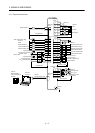
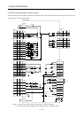
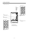
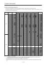
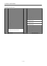
3. SIGNALS AND WIRING
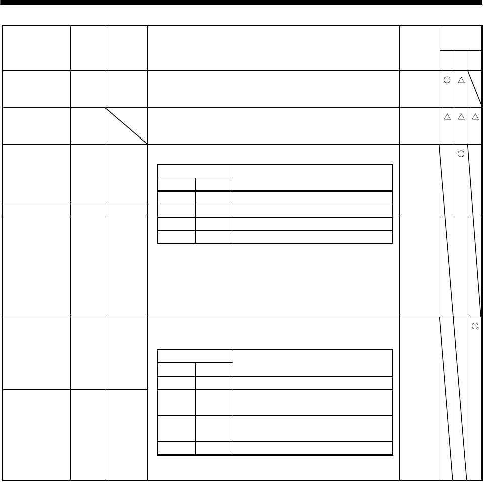
Control
mode
Signal Symbol
Connector
pin No.
Functions/Applications
I/O
division
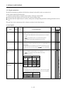
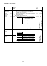
PST
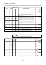
External torque
limit selection
TL CN1B
9
Turn TL off to make Internal torque limit 1 (parameter No. 28)
valid, or turn it on to make Analog torque limit (TLA) valid.
For details, refer to section 3.4.1 (5).
DI-1
Internal
torque limit
selection
TL1 When using this signal, make it usable by making the setting of
parameter No. 43 to 48.
For details, refer to section 3.4.1 (5).
DI-1
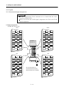
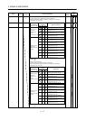
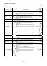
Used to start the servo motor in any of the following directions.
(Note) Input signals
ST2 ST1
Servo motor starting direction
Forward
rotation start
ST1 CN1B
8
0 0 Stop (servo lock)
0 1 CCW
10 CW
1 1 Stop (servo lock)
Reverse rotation
start
ST2 CN1B
9
Note. 0: off
1: on
If both ST1 and ST2 are switched on or off during operation, the
servo motor will be decelerated to a stop according to the
parameter No. 12 setting and servo-locked.
DI-1
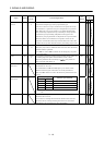
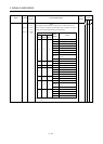
Used to select any of the following servo motor torque generation
directions.
(Note) Input signals
RS2 RS1
Torque generation direction
Forward
rotation
selection
RS1 CN1B
9
0 0 Torque is not generated.
01
Forward rotation in driving mode /
reverse rotation in regenerative mode
10
Reverse rotation in driving mode /
forward rotation in regenerative mode
1 1 Torque is not generated.
Reverse rotation
selection
RS2 CN1B
8
Note. 0: off
1: on
DI-1