


3 - 43
3. SIGNALS AND WIRING
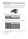
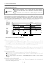
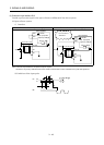
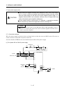
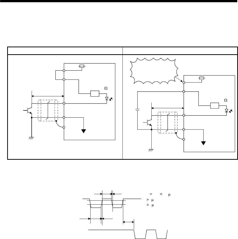
(3) Pulse train input interface DI-2
Provide a pulse train signal in the open collector or differential line driver system.
(a) Open collector system
1) Interface
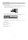
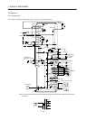
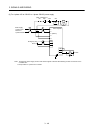
For use of internal power supply For use of external power supply
VDD
OPC
PP, NP
SG
SD
Max. input pulse
frequency 200kpps
About 1.2k
24VDC
2m (78.74in) or less
(Note)
Servo amplifier
24VDC
Do not connect
VDD-OPC.
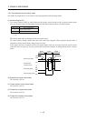
VDD
OPC
PP, NP
SG
SD
Max. input pulse
frequency 200kpps
About 1.2k
24VDC
2m (78.74in) or less
(Note)
Servo amplifier
Note. Pulse train input interface is comprised of a photo coupler.
Therefore, it may be any malfunctions since the current is reduced when connect a resistance to a pulse train signal line.
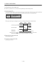
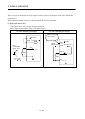
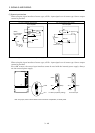
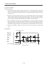
2) Conditions of the input pulse
0.9
0.1
tc
tHL
tc tLH
tF
tLH tHL 0.2 s
tc 2 s
tF 3 s
PP
NP