


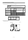
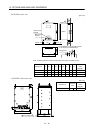
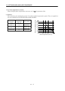
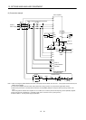
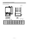
13 - 18
13. OPTIONS AND AUXILIARY EQUIPMENT
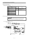
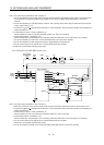
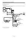
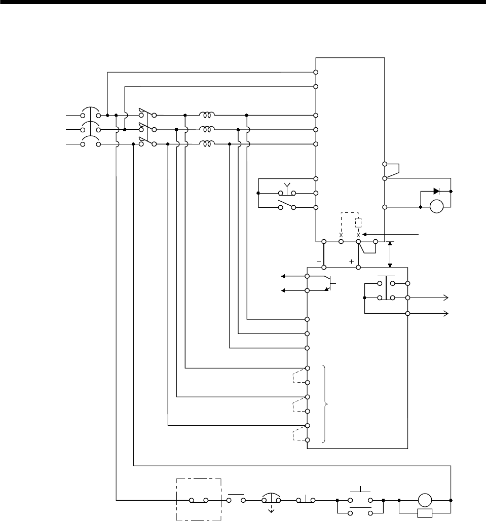
(2) Connection example
(Note 5)
Power supply
NFB
MC
Servo amplifier
L
11
L21
L
1
L
2
L3
SK
ON
MC
BC
RDY
SE
Alarm
output
RDY
output
A
B
C
Operation ready
MC
OFF
EMG
RA2
FR-RC
Ready
(Note 3) Power factor improving reactor
FR-BAL
R/L
1
S/L2
T/L3
B
C
EMG
SON
SG
COM
ALM
VDD
RA2
RRX
R
SX
S
TX
T
Phase detection
terminals
(Note 1)
Power regeneration
converter FR-RC
NP
5m(16.4ft) or less
N/ P/
(Note 2)
C
P
1
(Note 4)
Note 1. When not using the phase detection terminals, fit the jumpers across RX-R, SX-S and TX-T. If the jumpers remain removed, the
FR-RC will not operate.
2. For the servo amplifiers of 5k and 7kW, always remove the wiring (across P-C) of the built-in regenerative resistor.
3. Refer to the power return converter FR-RC instruction manual (IB(NA)-66330) for the power factor improving reactor to be
used.
When using FR-RC with the servo amplifier of 11k to 22kW, do not use the power factor improving reactor (FR-BEL) together.
4. When using the servo amplifier of 11k to 22kW, make sure to connect P
1
and P. (Factory-wired.)
5. Refer to section 1.3 for the power supply specification.