


5 - 16
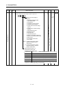
5. PARAMETERS
Class No. Symbol Name and function
Initial
value
Unit
Setting
range
Control
mode
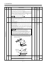
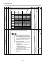
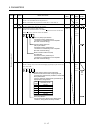
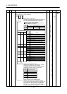
Analog speed command offset
Used to set the offset voltage of the analog speed command (VC).
For example, if CCW rotation is provided by switching on forward
rotation start (ST1) with 0V applied to VC, set a negative value.
When automatic VC offset is used, the automatically offset value is
set to this parameter. (Refer to section 6.3)
The initial value is the value provided by the automatic VC offset
function before shipment at the VC-LG voltage of 0V.
S
29 VCO
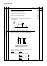
Analog speed limit offset
Used to set the offset voltage of the analog speed limit (VLA).
For example, if CCW rotation is provided by switching on forward
rotation selection (RS1) with 0V applied to VLA, set a negative value.
When automatic VC offset is used, the automatically offset value is
set to this parameter. (Refer to section 6.3)
The initial value is the value provided by the automatic VC offset
function before shipment at the VLA-LG voltage of 0V.
Depends
on servo
amplifier
mV 999
to
999
T
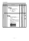
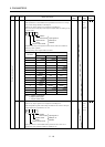
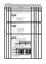
Analog torque command offset
Used to set the offset voltage of the analog torque command (TC).
T30 TLO
Analog torque limit offset
Used to set the offset voltage of the analog torque limit (TLA).
0mV999
to
999
S
31 MO1 Analog monitor 1 offset
Used to set the offset voltage of the analog monitor (MO1).
0
mV
999
to 999
P
S T
32 MO2 Analog monitor 2 offset
Used to set the offset voltage of the analog monitor (MO2).
0
mV
999
to 999
P
S T
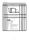
33 MBR Electromagnetic brake sequence output
Used to set the delay time (Tb) between electronic brake interlock
(MBR) and the base drive circuit is shut-off.
100 ms 0
to
1000
P
S T
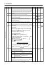
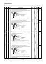
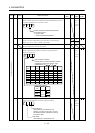
34 GD2 Ratio of load inertia moment to servo motor inertia moment
Used to set the ratio of the load inertia moment to the servo motor
shaft inertia moment. When auto tuning mode 1 and interpolation
mode is selected, the result of auto tuning is automatically used.
(Refer to section 7.1.1)
In this case, it varies between 0 and 1000.
70 0.1
times
0
to
3000
P
S
35 PG2 Position control gain 2
Used to set the gain of the position loop.
Set this parameter to increase the position response to level load
disturbance. Higher setting increases the response level but is liable
to generate vibration and/or noise.
When auto tuning mode 1,2 and interpolation mode is selected, the
result of auto tuning is automatically used.
7kW or
less: 35
11kW or
more: 19
rad/s 1
to
1000
P
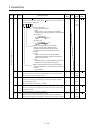
36 VG1 Speed control gain 1
Normally this parameter setting need not be changed.
Higher setting increases the response level but is liable to generate
vibration and/or noise.
When auto tuning mode 1
2, manual mode and interpolation mode
is selected, the result of auto tuning is automatically used.
7kW or
less: 177
11kW or
more: 96
rad/s 20
to
8000
P
S
37 VG2 Speed control gain 2
Set this parameter when vibration occurs on machines of low rigidity
or large backlash. Higher setting increases the response level but is
liable to generate vibration and/or noise.
When auto tuning mode 1
2 and interpolation mode is selected, the
result of auto tuning is automatically used.
7kW or
less: 817
11kW or
more: 45
rad/s 20
to
20000
P
S
Expansion parameters 1
38 VIC Speed integral compensation
Used to set the integral time constant of the speed loop.
Lower setting increases the response level but is liable to generate
vibration and/or noise.
When auto tuning mode 1
2 and interpolation mode is selected, the
result of auto tuning is automatically used.
7kW or
less: 48
11kW or
more: 91
ms 1
to
1000
P
S