


3 - 42
3. SIGNALS AND WIRING
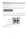
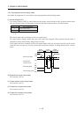
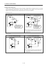
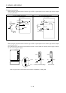
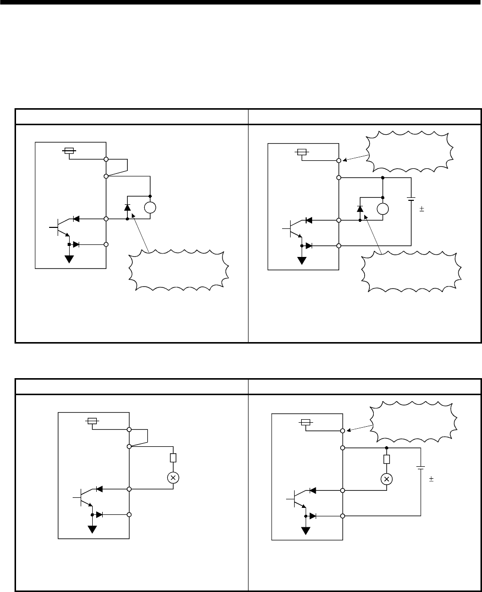
(2) Digital output interface DO-1
A lamp, relay or photocoupler can be driven. Provide a diode (D) for an inductive load, or an inrush
current suppressing resistor (R) for a lamp load. (Permissible current: 40mA or less, inrush current:
100mA or less) A maximum of 2.6V voltage drop occurs in the servo amplifier.
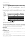
(a) Inductive load
For use of internal power supply For use of external power supply
COM
ALM, etc
SG
Load
Servo amplifier
VDD
24VDC
If the diode is not
connected as shown,
the servo amplifier
will be damaged.
COM
ALM, etc
SG
Load
Servo amplifier
VDD
24VDC
If the diode is not
connected as shown,
the servo amplifier
will be damaged.
Do not connect
VDD-COM.
(Note)
24VDC
10%
Note. If the voltage drop (maximum of 2.6V) interferes with the
relay operation, apply high voltage (up to 26.4V) from
external source.
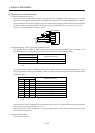
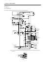
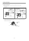
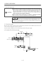
(b) Lamp load
For use of internal power supply For use of external power supply
Servo amplifier
COM
R
VDD
24VDC
SG
ALM, etc
(Note)
24VDC
10%
Servo amplifier
COM
R
VDD
24VDC
SG
ALM, etc
Do not connect
VDD-COM.
Note. If the voltage drop (maximum of 2.6V) interferes with the
relay operation, apply high voltage (up to 26.4V) from
external source.