


8 - 6
8. SPECIAL ADJUSTMENT FUNCTIONS
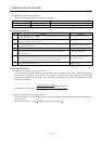
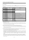
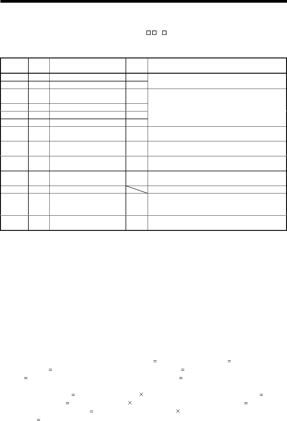
8.5.3 Parameters
When using the gain changing function, always set "
4 " in parameter No.2 (auto tuning) to choose
the manual mode of the gain adjustment modes. The gain changing function cannot be used in the auto
tuning mode.
Parameter
No.
Abbrevi
ation
Name Unit Description
6PG1Position control gain 1 rad/s
36 VG1 Speed control gain 1 rad/s
Position and speed gains of a model used to set the response
level to a command. Always valid.
34 GD2
Ratio of load inertia moment to
servo motor inertia moment
0.1
times
35 PG2 Position control gain 2 rad/s
37 VG2 Speed control gain 2 rad/s
38 VIC Speed integral compensation ms
Control parameters before changing
61 GD2B
Ratio of load inertia moment to
servo motor inertia moment 2
0.1
times
Used to set the ratio of load inertia moment to servo motor
inertia moment after changing.
62 PG2B
Position control gain 2 changing
ratio
%
Used to set the ratio (%) of the after-changing position
control gain 2 to position control gain 2.
63 VG2B
Speed control gain 2 changing
ratio
%
Used to set the ratio (%) of the after-changing speed control
gain 2 to speed control gain 2.
64 VICB
Speed integral compensation
changing ratio
%
Used to set the ratio (%) of the after-changing speed integral
compensation to speed integral compensation.
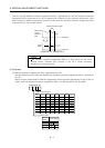
65 CDP Gain changing selection Used to select the changing condition.
66 CDS Gain changing condition
kpps
pulse
r/min
Used to set the changing condition values.
67 CDT Gain changing time constant ms
You can set the filter time constant for a gain change at
changing.
(1) Parameters No. 6, 34 to 38
These parameters are the same as in ordinary manual adjustment. Gain changing allows the values of
ratio of load inertia moment to servo motor inertia moment, position control gain 2, speed control gain
2 and speed integral compensation to be changed.
(2) Ratio of load inertia moment to servo motor inertia moment 2 (GD2B: parameter No. 61)
Set the ratio of load inertia moment to servo motor inertia moment after changing. If the load inertia
moment ratio does not change, set it to the same value as ratio of load inertia moment to servo motor
inertia moment (parameter No. 34).
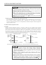
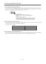
(3) Position control gain 2 changing ratio (parameter No. 62), speed control gain 2 changing ratio (parameter
No. 63), speed integral compensation changing ratio (parameter No. 64)
Set the values of after-changing position control gain 2, speed control gain 2 and speed integral
compensation in ratio (%). 100% setting means no gain change.
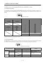
For example, at the setting of position control gain 2
100, speed control gain 2
2000, speed integral
compensation
20 and position control gain 2 changing ratio
180%, speed control gain 2 changing
ratio
150% and speed integral compensation changing ratio
80%, the after-changing values are as
follows.
Position control gain 2
Position control gain 2
Position control gain 2 changing ratio /100 180rad/s
Speed control gain 2
Speed control gain 2
Speed control gain 2 changing ratio /100
3000rad/s
Speed integral compensation
Speed integral compensation Speed integral compensation changing
ratio /100
16ms